LG ANEH153B2 - Manuals
LG ANEH153B2 Air Conditioner – User Manual in PDF format online.
Manuals:
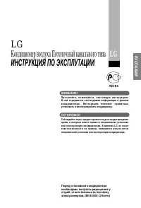
User Manual LG ANEH153B2


Summary
2 Auxiliary Heat Control IMPORTANT! CAUTION: Improper installation, adjustment, alteration, service or maintenance can void the warranty.The weight of the condensing unit requires caution and proper handling procedures when liftingor moving to avoid personal injury. Use care to avoid contact with sh...
Table of contents Installation Manual 3 ENGLISH 4 Safety Precautions 5 Included Items 6 Minimum airflow by heater capacity 6 Auxiliary Heat Control Static pressure drop factors 6 Available power cable 7 Assembly Diagram 11 Electrical Wiring TABLE OF CONTENTS
4 Auxiliary Heat Control To prevent injury to the user or other people and property damage, the following instructionsmust be followed. n Incorrect operation due to ignoring instruction will cause harm or damage. The seriousnessis classified by the following indications. n Meanings of symbols used i...
LG Air Conditioners Manuals
-
 LG B24TS
User Manual
LG B24TS
User Manual
-
LG B24TS
Manual
-
 LG B60LH
User Manual
LG B60LH
User Manual
-
 LG LB-H368GSS0
User Manual
LG LB-H368GSS0
User Manual
-
 LG LP0621WSR
User Manual
LG LP0621WSR
User Manual
-
 LG LP0721WSR
User Manual
LG LP0721WSR
User Manual
-
 LG LP0821GSSM
User Manual
LG LP0821GSSM
User Manual
-
 LG LP1021BHSM
User Manual
LG LP1021BHSM
User Manual
-
 LG LP1021BSSM
User Manual
LG LP1021BSSM
User Manual
-
 LG LP1419IVSM
User Manual
LG LP1419IVSM
User Manual
-
 LG LT1016CER
User Manual
LG LT1016CER
User Manual
-
 LG LT1216CER
User Manual
LG LT1216CER
User Manual
-
 LG LT-B2861HL
User Manual
LG LT-B2861HL
User Manual
-
 LG LW1016ER
User Manual
LG LW1016ER
User Manual
-
 LG LW1017ERSM
User Manual
LG LW1017ERSM
User Manual
-
 LG LW1017ERSM1
User Manual
LG LW1017ERSM1
User Manual
-
 LG LW1216ER
User Manual
LG LW1216ER
User Manual
-
 LG LW1217ERSM1
User Manual
LG LW1217ERSM1
User Manual
-
 LG LW1221HRSM
User Manual
LG LW1221HRSM
User Manual
-
 LG LW1223HR
User Manual
LG LW1223HR
User Manual