Page 3 - ENG; English; TABLE OF CONTENTS
2 ENG English Table of Contents TABLE OF CONTENTS 3 ASSEMBLING AND PREPARING 3 Unpacking 4 Parts and buttons 5 Lifting and moving the Monitor 5 Setting Up the Monitor set 5 - Attaching the Stand Base 6 - Mounting on a table 6 - Adjusting the angle 7 - Adjusting the stand height 7 - Using the Kensing...
Page 4 - ASSEMBLING AND PREPARING; Unpacking; Power Cord; CAUTION; Stand Base
3 ENG English ASSEMBLING AND PREPARING ASSEMBLING AND PREPARING Unpacking Please check whether all the components are included in the box before using the product. If there are missing components, contact the retail store where you purchased the product. Note that the product and components may look...
Page 5 - Parts and buttons; Power Indicator
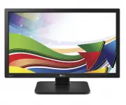
4 ENG English ASSEMBLING AND PREPARING 1 1 Parts and buttons Power Indicator y y LED On : Power is on y y LED Off: Power is off Front Side Buttons Input Connectors (See p.12 to 15) (Power Button) Input Connectors (See p.15 )
Page 6 - Setting Up the Monitor set; Attaching the Stand Base; stand base; Stand Body; Lifting and moving the
5 ENG English ASSEMBLING AND PREPARING Setting Up the Monitor set Attaching the Stand Base 1 Place the monitor's screen face down. y y To protect the screen from scratches, cover the surface with a soft cloth. 3 Using a coin, turn the screw clockwise to se- cure the stand base. 2 Check the position ...
Page 7 - Adjusting the angle; Mounting on a table; Front Side
6 ENG English ASSEMBLING AND PREPARING Adjusting the angle 1 Place the monitor mounted on the stand base in an upright position. 2 Adjust the angle of the screen. The angle of the screen can be adjusted up to 5° forwards and 35° backwards for a comfortable viewing experience. y To avoid injury to th...
Page 8 - Using the Kensington locking; NOTE; Adjusting the stand height
7 ENG English ASSEMBLING AND PREPARING Using the Kensington locking device The connector for the Kensington lock is located on the rear of the monitor. For more information on installation and usage, refer to the Kensington lock user manual or visit the website at http://www.kensington.com. Connect ...
Page 9 - Detaching the stand body; Using the cable holder
8 ENG English ASSEMBLING AND PREPARING Detaching the stand body 1 Place the monitor's screen face down. To protect the screen from scratches, cover the surface with a soft cloth. 2 Using a screwdriver, remove the four screws and detach the stand from the monitor. y The components appearing in the il...
Page 10 - Swivel stand; Head
9 ENG English ASSEMBLING AND PREPARING Swivel stand y Image shown may differ from your Monitor set. 1 Swivel 355 degrees and adjust the angle of the Monitor set to suit your view. 1 Lift the monitor to its highest height to utilize the Pivot function. Using the Pivot function The pivot function allo...
Page 11 - Mounting on a wall; Wall Mount Plate
10 ENG English ASSEMBLING AND PREPARING 3.94 inches 3.94 inches 3.94 inches 3.94 inches If you intend to mount the Monitor set to a wall, attach Wall mounting interface (optional parts) to the back of the set. When you install the Monitor set using a wall mounting interface (optional parts), attach ...
Page 13 - USING THE MONITOR SET; Connecting Input Signal Cable; Apple Adapter
12 ENG English USING THE MONITOR SET USING THE MONITOR SET Connecting Input Signal Cable y y This monitor supports the *Plug and Play feature.*Plug and Play: A feature that allows you to add a device to your computer, without having to reconfigure anything or install any manual drivers. D-SUB IN con...
Page 14 - DVI connection
13 ENG English USING THE MONITOR SET DVI connection Transfers digital video signals from the Cloud Mon-itor to an extended monitor.Connect the Cloud Monitor to an extended monitor using a DVI cable. y y To connect the monitor to a computer, use the appropriate signal cable (LAN and D-SUB). y y A con...
Page 15 - Connecting LAN/Peripherals; LAN connection
14 ENG English USING THE MONITOR SET Connecting LAN/Peripherals LAN connection Connect the router or switch to the monitor using a LAN cable as illustrated below. y y The LAN cable is sold separately. y y The following LAN cable type can be used: Standard: IEEE 802.3 ETHERNET y y If a device is conn...
Page 16 - Peripheral device connection; Left
15 ENG English USING THE MONITOR SET y y Peripheral devices are sold separately. y y The USB ports on the left and bottom of the monitor can be used to connect the key-board, mouse, and other USB devices. y y Cables with angled plugs may have clear-ance issues, use straight plugs when pos-sible. Ang...
Page 17 - Self Image Adjustment
16 ENG English USING THE MONITOR SET y y What is "Self Image Adjustment"? This func-tion runs when the monitor is connected for the first time and performs automatic image adjustment for each signal (only available for analog [D-SUB input] signals) to provide an optimal screen display. Self ...
Page 18 - CUSTOMIZING SETTINGS; EXIT; Monitor set Buttons
17 ENG English CUSTOMIZING SETTINGS CUSTOMIZING SETTINGS 1 Press the desired button on the bottom of the Monitor set. 2 Change the value of the menu item by pressing the buttons on the bottom of the Monitor set. To return to the upper menu or set other menu items, use the up arrow ( ) button. 3 Sele...
Page 19 - Customizing Settings; Menu Settings; MENU
18 ENG English CUSTOMIZING SETTINGS Customizing Settings Menu Settings 1 Press MENU button on the bottom of the Monitor set to display the Menu OSD. 2 Set the options by pressing the ◄ or ► or ▼ buttons. 3 Select the " Next Menu " button to enter the more option settings. 4 Select EXIT to le...
Page 20 - Picture
19 ENG English CUSTOMIZING SETTINGS Picture 1 Press Menu button on the bottom of the Monitor set to display the Menu OSD. 2 Select the " Next Menu " button to enter the more option settings. 3 Enter to Picture by pressing the ▼ button. 4 Set the options by pressing the ◄ or ► buttons. 5 Sele...
Page 21 - Color
20 ENG English CUSTOMIZING SETTINGS Color 1 Press MENU button on the bottom of the Monitor set to display the Menu OSD. 2 Select the " Next Menu " button to enter the more option settings. 3 Select Color by pressing the ► button. 4 Enter to Color by pressing the ▼ button. 5 Set the options b...
Page 22 - Display
21 ENG English CUSTOMIZING SETTINGS Display 1 Press MENU button on the bottom of the Monitor set to display the Menu OSD. 2 Select the " Next Menu " button to enter the more option settings. 3 Select Display by pressing the ► button. 4 Enter to Display by pressing the ▼ button. 5 Set the opt...
Page 23 - Others
22 ENG English CUSTOMIZING SETTINGS Others 1 Press MENU button on the bottom of the Monitor set to display the Menu OSD. 2 Select the " Next Menu " button to enter the more option settings. 3 Select Others by pressing the ► button. 4 Enter to Others by pressing the ▼ button. 5 Set the option...
Page 24 - VOL
23 ENG English CUSTOMIZING SETTINGS Volume 1 Press the VOL button at the bottom of the monitor to display the VOL OSD menu. 2 Press the ◄ or ► button to adjust the volume. 3 Press the button to enable or disable Mute. 4 Select EXIT to leave the OSD menu. Each option is explained below. Volume Descri...
Page 25 - TROUBLESHOOTING; Horizontal Frequency:; Check the following before calling for service.; AUTO
24 ENG English Troubleshooting TROUBLESHOOTING y y Vertical Frequency: In order to display an image, the screen must be refreshed dozens of times per second like a fluorescent lamp. The number of times the screen is refreshed per second is called vertical frequency or refresh rate and is represented...
Page 27 - PRODUCT SPECIFICATION
26 ENG English Product Specification PRODUCT SPECIFICATION LCD Screen Type TFT (Thin Film Transistor) LCD (Liquid Crystal Display) Screen Pixel Pitch 0.2745 mm x 0.2745 mm Resolution Maximum Resolution 1920 x 1080 @ 60 Hz Recommended Resolution 1920 x 1080 @ 60 Hz Video Signal Horizontal Frequency 3...
Page 28 - Preset Mode; Indicator
27 ENG English Product Specification Preset Mode Display Modes (Resolution) Horizontal Frequency (kHz) Vertical Frequency (Hz) Polarity (H/V) Remark 720 x 400 31.468 70.08 -/+ 640 x 480 31.469 59.94 -/- 800 x 600 37.879 60.317 +/+ 1024 x 768 48.363 60 -/- 1280 x 1024 63.981 60.02 +/+ 1680 x 1050 65....
Page 29 - PROPER POSTURE; Proper posture for using the monitor
28 ENG English Proper Posture PROPER POSTURE Proper posture for using the monitor Adjust the angle so that the screen is slightly lower than your eyes. y y Using the monitor for a prolonged period of time can cause eye fatigue. Take a 10-minute break every hour. y y The stand is designed to best sup...
Page 30 - USING CLOUD SOLUTION; Connect Screen
29 ENG English Using CLOUD Solution USING CLOUD SOLUTION If the network is connected and IP is being ac-quired, the message "Network connection detect-ed. Acquiring IP address …" is displayed on the Connection screen. Figure 2-3 shows the message displayed when the network is ready and the I...
Page 36 - Session Tab; Connection Type
35 ENG English Using CLOUD Solution <Figure 2-12: Session Configuration> Session Tab The Session tab allows the administrator to set the method to connect the device to a peer device. y y The Session parameters can also be con-figured using the Webpage Administration Interface. NOTE y Connecti...
Page 37 - Wake Host from Low Power State
36 ENG English Using CLOUD Solution y Wake Host from Low Power State Select whether to use the host’s MAC address or IP address when configuring the Wake-On-LAN feature for a client. This feature wakes up the host when the user presses the client’s remote PC button or clicks the connect button on th...
Page 38 - Enable Peer Loss Overlay; Enable Preparing Desktop Overlay
37 ENG English Using CLOUD Solution <Figure 2-16: Direct to Host + SLP Host Discovery Set- tings> y y This setting is provided only for the client. NOTE y Enable Peer Loss Overlay The "Connection Lost" message is displayed.The display is the same as in the VDI environ-ment. The default...
Page 51 - PCoIP Packets Statistics; Session Statistics Tab; PCoIP Processor Tab
50 ENG English Using CLOUD Solution y PCoIP Packets Statistics y PCoIP Packets SentThe PCoIP Packets Sent field shows the total number of PCoIP packets sent from the portal to the host in the last active session. y PCoIP Packets Received The PCoIP Packets Received field shows the total number of PCo...
Page 57 - Declaration of Conformity
MODEL SERIAL Make sure to read the Safety Precautions before using the product. Keep the Owner’s Manual (CD) in an accessible place for future reference. The model and serial number of the SET is located on the back and one side of the SET. Record it below should you ever need service. To obtain the...