KitchenAid KOCE500EBS - Manuals
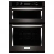
User Manual KitchenAid KOCE500EBS


Manual KitchenAid KOCE500EBS


Summary
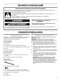
2 BUILT-IN OVEN SAFETY INSTALLATION REQUIREMENTS Tools and Parts Gather the required tools and parts before starting installation. Read and follow the instructions provided with any tools listed here. Tools Needed ■ Phillips screwdriver ■ Measuring tape ■ Drill (for wall cabinet installations) ■ ¹⁄₈...
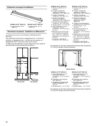
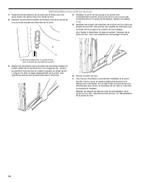
3 Cabinet Dimensions - Flush Installations A 25 ³⁄₈ " (64.4 cm) minimum cutout depth is required. These dimensions will result in a ¹⁄₄ " (6 mm) reveal on the top, a ¹⁄₄ " (6 mm) reveal on the sides, and a ¹⁄₈ " (3 mm) reveal on the bottom of the wall oven. The front face of the clea...
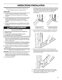
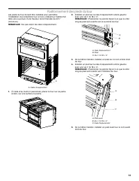
4 INSTALLATION INSTRUCTIONS Prepare Built-In Microwave/Oven Combination NOTES: ■ Refer to the following “Installation Instructions” and the “Installation Instructions” section of the Installation Instructions provided with your built-in microwave/oven combination. ■ Refer and adhere to the “Electric...
KitchenAid Ovens Manuals
-
 KitchenAid KOCE500EBL
User Manual
KitchenAid KOCE500EBL
User Manual
-
 KitchenAid KOCE500ESS
User Manual
KitchenAid KOCE500ESS
User Manual
-
KitchenAid KOCE500ESS
Manual
-
 KitchenAid KOCE507ESS
User Manual
KitchenAid KOCE507ESS
User Manual
-
KitchenAid KOCE507ESS
Manual
-
KitchenAid KOCE507ESS
Installation Manual
-
 KitchenAid KOCE900HBS
Installation Manual
KitchenAid KOCE900HBS
Installation Manual
-
 KitchenAid KOCE900HSS
User Manual
KitchenAid KOCE900HSS
User Manual
-
KitchenAid KOCE900HSS
Installation Manual
-
KitchenAid KOCE900HSS
Manual
-
 KitchenAid KODC504PPS
User Manual
KitchenAid KODC504PPS
User Manual
-
KitchenAid KODC504PPS
Installation Manual
-
KitchenAid KODC504PPS
Manual
-
 KitchenAid KODE300ESS
User Manual
KitchenAid KODE300ESS
User Manual
-
 KitchenAid KODE500EBS
User Manual
KitchenAid KODE500EBS
User Manual
-
KitchenAid KODE500EBS
Manual
-
 KitchenAid KODE500ESS
User Manual
KitchenAid KODE500ESS
User Manual
-
KitchenAid KODE500ESS
Manual
-
 KitchenAid KODE507EBS
User Manual
KitchenAid KODE507EBS
User Manual
-
 KitchenAid KODE507ESS
User Manual
KitchenAid KODE507ESS
User Manual