Haier KC18AGH- Manuals
Haier KC18AGH– User Manual in PDF format online.
Manuals:
User Manual Haier KC18AGH


Summary
Pub. OI-85264181002000 © SANYO 2010 SANYO Electric Co., Ltd. Save These Instructions! INSTRUCTION MANUAL Split System Air Conditioner COOL / DRY MODEL SAP-K18AM / AMS HEAT PUMP MODEL H A 1 - P H A 2 1 K - P A S INDOOOR UNIT OUTDOOR UNIT SAP-C18AM / AMS SAP-K18AGH SAP-C18AGH
Contents Alert Symbols The following symbols used in this manual, alert you to potentially dangerous conditions to users, service personnel Thank you for choosing SANYO air conditioner, please read this instruction manual carefully before operating the unit and keep it carefully for consultation. Th...
EG 1. NOTICES FOR OPERATION 2 The wrong repair will lead to anelectric shock or fire, so youshould contact the SANYOservice center for repair. Select the most appropriate temperature. It can help to preclude theelectricity wasted. Keep roomcooler thanoutside about 5 C. It can decrease the airconditi...
Haier Manuals
-
 Haier HF11CM10NW
User Manual
Haier HF11CM10NW
User Manual
-
Haier HF11CM10NW
Manual
-
 Haier BCF46B
User Manual
Haier BCF46B
User Manual
-
 Haier HCC2230AGS
User Manual
Haier HCC2230AGS
User Manual
-
Haier HCC2230AGS
Installation Manual
-
 Haier HLTD500ACW
User Manual
Haier HLTD500ACW
User Manual
-
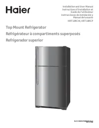 Haier HRT18RCPB1
User Manual
Haier HRT18RCPB1
User Manual
-
 Haier HVTS18DTBB
User Manual
Haier HVTS18DTBB
User Manual
-
Haier HRT18RCWB1
User Manual
-
 Haier HRT18R1APB
User Manual
Haier HRT18R1APB
User Manual
-
 Haier ESA3159
User Manual
Haier ESA3159
User Manual
-
 Haier CPN11XCJ
User Manual
Haier CPN11XCJ
User Manual
-
Haier HLTD500AEW
User Manual
-
 Haier PBFS21EDAS
User Manual
Haier PBFS21EDAS
User Manual
-
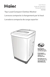 Haier HLP24E
User Manual
Haier HLP24E
User Manual
-
 Haier DWL4035DBWW
User Manual
Haier DWL4035DBWW
User Manual
-
Haier ESA3189
User Manual
-
 Haier CPN12XH9
User Manual
Haier CPN12XH9
User Manual
-
Haier CPN10XCJ
User Manual
-
Haier PBFS21EDBP
User Manual