Haier HSU18VH7- Manuals
Haier HSU18VH7– User Manual in PDF format online.
Manuals:
User Manual Haier HSU18VH7


Summary
Air conditioner Edition: 10070808 CONTENTS 1. GENERAL INFORMATION................................................................1 2. SPECIFICATION................................................................................3 3. ELECTRICAL CONTROL S ..................................................
Air conditioner Edition: 10070 8 0 8 - 1 - 1. General information This Service Manual describes the operation, disassembly, troubleshooting, and repair of Haier Room Air Conditioners, etc. It is intended for use by authorized services who troubleshoot and repair these units. It is assumed that users...
HSU18VH7 10070808 Product Features FAN SPEED TEMP SI GN AL SENDING SLEEP HEALTH POWER ON/OFF 18000/17800 BTU 1580/1560W/7/7.5A SEER:13.0/13.0 18000/18000 BTU 1520/1480W/6.7/7.2A HSPF:7.7/7.7 500 CFM 1PH 230/208V ~ 60Hz
Haier Manuals
-
 Haier HF11CM10NW
User Manual
Haier HF11CM10NW
User Manual
-
Haier HF11CM10NW
Manual
-
 Haier BCF46B
User Manual
Haier BCF46B
User Manual
-
 Haier HCC2230AGS
User Manual
Haier HCC2230AGS
User Manual
-
Haier HCC2230AGS
Installation Manual
-
 Haier HLTD500ACW
User Manual
Haier HLTD500ACW
User Manual
-
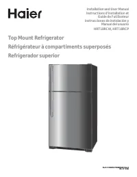 Haier HRT18RCPB1
User Manual
Haier HRT18RCPB1
User Manual
-
 Haier HVTS18DTBB
User Manual
Haier HVTS18DTBB
User Manual
-
Haier HRT18RCWB1
User Manual
-
 Haier HRT18R1APB
User Manual
Haier HRT18R1APB
User Manual
-
 Haier ESA3159
User Manual
Haier ESA3159
User Manual
-
 Haier CPN11XCJ
User Manual
Haier CPN11XCJ
User Manual
-
Haier HLTD500AEW
User Manual
-
 Haier PBFS21EDAS
User Manual
Haier PBFS21EDAS
User Manual
-
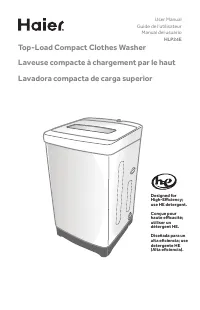 Haier HLP24E
User Manual
Haier HLP24E
User Manual
-
 Haier DWL4035DBWW
User Manual
Haier DWL4035DBWW
User Manual
-
Haier ESA3189
User Manual
-
 Haier CPN12XH9
User Manual
Haier CPN12XH9
User Manual
-
Haier CPN10XCJ
User Manual
-
Haier PBFS21EDBP
User Manual