Haier 309292L - Manuals
Haier 309292L – Manual in PDF format online.
Manuals:
Manual Haier 309292L


Summary
2 309292L Table of Contents List of Models . . . . . . . . . . . . . . . . . . . . . . . . . . . . . 3 Symbols . . . . . . . . . . . . . . . . . . . . . . . . . . . . . . . . . . 4 Warning . . . . . . . . . . . . . . . . . . . . . . . . . . . . . . . . . . . 4 Introduction . . . . . . . . . . . . . ...
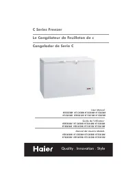
List of Models 309292L 3 List of Models Part No. Model Smart Display Type of Coatings Operation Manual Standard High Conductivity 244400, Series C PRO Xs3 X 309294/3W9294/3Z9294 244579, Series C PRO Xs3 X X 309294/3W9294/3Z9294 244575, Series C PRO Xs3 X 309294/3W9294/3Z9294 244576, Series C PRO Xs3...
Symbols 4 309292L Symbols Warning Symbol This symbol alerts you to the possibility of serious injury or death if you do not follow the instructions. Caution Symbol This symbol alerts you to the possibility of damage to or destruction of equipment if you do not follow the instruc-tions. WARNING CAUTI...
Haier Manuals
-
 Haier HF11CM10NW
User Manual
Haier HF11CM10NW
User Manual
-
Haier HF11CM10NW
Manual
-
 Haier BCF46B
User Manual
Haier BCF46B
User Manual
-
 Haier HCC2230AGS
User Manual
Haier HCC2230AGS
User Manual
-
Haier HCC2230AGS
Installation Manual
-
 Haier HLTD500ACW
User Manual
Haier HLTD500ACW
User Manual
-
 Haier HRT18RCPB1
User Manual
Haier HRT18RCPB1
User Manual
-
 Haier HVTS18DTBB
User Manual
Haier HVTS18DTBB
User Manual
-
Haier HRT18RCWB1
User Manual
-
 Haier HRT18R1APB
User Manual
Haier HRT18R1APB
User Manual
-
 Haier ESA3159
User Manual
Haier ESA3159
User Manual
-
 Haier CPN11XCJ
User Manual
Haier CPN11XCJ
User Manual
-
Haier HLTD500AEW
User Manual
-
 Haier PBFS21EDAS
User Manual
Haier PBFS21EDAS
User Manual
-
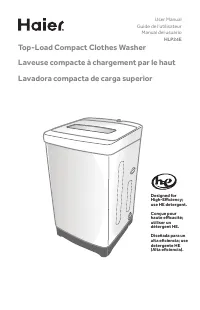 Haier HLP24E
User Manual
Haier HLP24E
User Manual
-
 Haier DWL4035DBWW
User Manual
Haier DWL4035DBWW
User Manual
-
Haier ESA3189
User Manual
-
 Haier CPN12XH9
User Manual
Haier CPN12XH9
User Manual
-
Haier CPN10XCJ
User Manual
-
Haier PBFS21EDBP
User Manual