Haier 237410 - Manuals
Haier 237410 – Manual in PDF format online.
Manuals:
Manual Haier 237410


Summary
3X8–448 Rev. F Supersedes Rev. C Includes Rev. D and E changes Parts Change Notice Some parts in Rev. C of manual 308–448 have changed but have not yet been changed in theinstruction manual. Please note the changes below and mark them in your manual or keep thissheet with your manual. Assembly No. S...
Table of Contents Symbols W a r n i n g s . . . . . . . . . . . . . . . . . . . . . . . . . . . . . . . . . . . . . . 2 S e t u p . . . . . . . . . . . . . . . . . . . . . . . . . . . . . . . . . . . . . . . . . 4 System Component Information . . . . . . . . . . . . . . . . . . 6 Operation . . . . ....
EQUIPMENT MISUSE HAZARD Equipment misuse can cause the equipment to rupture, malfunction, or start unexpectedly and resultin serious injury. l This equipment is for professional use only. Read all instruction manuals, tags, and labels before operating the equipment. Use the equipment only for its in...
Haier Manuals
-
 Haier HF11CM10NW
User Manual
Haier HF11CM10NW
User Manual
-
Haier HF11CM10NW
Manual
-
 Haier BCF46B
User Manual
Haier BCF46B
User Manual
-
 Haier HCC2230AGS
User Manual
Haier HCC2230AGS
User Manual
-
Haier HCC2230AGS
Installation Manual
-
 Haier HLTD500ACW
User Manual
Haier HLTD500ACW
User Manual
-
 Haier HRT18RCPB1
User Manual
Haier HRT18RCPB1
User Manual
-
 Haier HVTS18DTBB
User Manual
Haier HVTS18DTBB
User Manual
-
Haier HRT18RCWB1
User Manual
-
 Haier HRT18R1APB
User Manual
Haier HRT18R1APB
User Manual
-
 Haier ESA3159
User Manual
Haier ESA3159
User Manual
-
 Haier CPN11XCJ
User Manual
Haier CPN11XCJ
User Manual
-
Haier HLTD500AEW
User Manual
-
 Haier PBFS21EDAS
User Manual
Haier PBFS21EDAS
User Manual
-
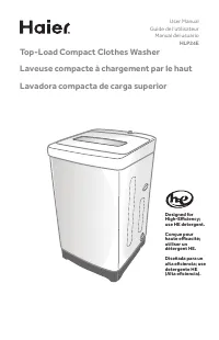 Haier HLP24E
User Manual
Haier HLP24E
User Manual
-
 Haier DWL4035DBWW
User Manual
Haier DWL4035DBWW
User Manual
-
Haier ESA3189
User Manual
-
 Haier CPN12XH9
User Manual
Haier CPN12XH9
User Manual
-
Haier CPN10XCJ
User Manual
-
Haier PBFS21EDBP
User Manual