Page 2 - Contents
Contents 2 334659A Contents Warnings . . . . . . . . . . . . . . . . . . . . . . . . . . . . . . . . . . . . . . . . . . . . . . . . . . . . . . . . . . . . . 3Component Identification . . . . . . . . . . . . . . . . . . . . . . . . . . . . . . . . . . . . . . . . . . . . . . . . 7 Stand Model . . ....
Page 3 - Warnings
Warnings 334659A 3 Warnings The following warnings are for the setup, use, grounding, maintenance, and repair of this equipment. The exclamation point symbol alerts you to a general warning and the hazard symbols refer to procedure-specific risks. When these symbols appear in the body of this manual...
Page 7 - Component Identification; Stand Model
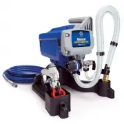
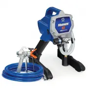
Component Identification 334659A 7 Component Identification Stand Model U K S M N V P R A B D ti25254a J G F L H A ON/OFF Switch B Pressure Control D Prime ValveF Tip Guard G Spray TipH GunJ Airless Hose K Power Cord L Trigger Lock M Drain TubeN Fluid IntakeP Pump R Fluid OutletS Power Cord Wrap U F...
Page 9 - Grounding; Power Requirements
Grounding 334659A 9 Grounding This sprayer includes a ground wire with an appropriate ground contact.The plug must be plugged into an outlet that is properly installed and grounded in accordance with all local codes and ordinances.Do not modify the plug provided; if it does not fit the outlet, have ...
Page 11 - Trigger Lock
Pressure Relief Procedure 334659A 11 6. Put drain tube in pail. Turn prime valve down. Leave prime valve in down (drain) position until you are ready to spray again. 7. If you suspect the spray tip or hose is clogged or that pressure has not been fully relieved: a. VERY SLOWLY loosen tip guard retai...
Page 12 - Setup
Setup 12 334659A Setup When unpacking sprayer for the first time or after long term storage perform setup procedure. When first setup is performed remove shipping plug from fluid outlet.1. Connect Graco airless hose to fluid outlet. Use wrenches to tighten securely. 2. Connect other end of hose to g...
Page 15 - Startup
Startup 334659A 15 Startup 1. Perform Pressure Relief Procedure , page 10. 2. Turn pressure control to lowest pressure. 3. Turn ON/OFF switch to ON position. 4. Place fluid intake in paint pail. Place drain tube in waste pail. 5. Increase pressure 1/2 turn to start motor. Allow paint to circulate th...
Page 17 - Operation; Spray Tip Installation; Spray
Operation 334659A 17 Operation Spray Tip Installation 1. Perform Pressure Relief Procedure , page 10. 2. Use spray tip (A) to insert OneSeal ™ (B) into tip guard (C). 2. Insert Spray Tip. 3. Screw assembly onto gun. Tighten. Spray 1. Spray test pattern. Adjust pressure to eliminate heavy edges. ti24...
Page 18 - Clear Tip Clog
Operation 18 334659A 2. Use smaller tip size if pressure adjustment cannot eliminate heavy edges. 3. Hold gun perpendicular, 10-12 in. (25-30 cm) from surface. Spray back and forth; overlap by 50%. 4. Trigger gun after moving. Release trigger before stopping. For additional spraying information, see...
Page 19 - Cleanup
Operation 334659A 19 Cleanup 1. Perform Pressure Relief Procedure , page 10. 2. Remove tip guard and Spray Tip. For additional information, see separate gun manual. 3. Remove fluid intake and drain tube from paint, wipe excess paint off outside. 4. Place fluid intake in flushing fluid. Use water for...
Page 22 - Maintenance
Maintenance 22 334659A Maintenance Routine maintenance is important to ensure proper operation of your sprayer. Maintenance includes performing routine actions which keep your sprayer in operation and prevents trouble in the future. Activity Interval Inspect/clean sprayer filter, fluid inlet straine...
Page 23 - Troubleshooting; Mechanical/Fluid Flow
Troubleshooting 334659A 23 Troubleshooting Mechanical/Fluid Flow 1. Follow Pressure Relief Procedure , page 10, before checking or repairing. 2. Check all possible problems and causes before disassembling the unit. Problem What to Check If check is OK, go to next check What to Do When check is not O...
Page 26 - Electrical
Troubleshooting 26 334659A Electrical Symptom: Sprayer does not run, stops running, or will not shut off. Perform Pressure Relief Procedure , page 10.1. Plug sprayer into correct voltage, grounded outlet. 2. Turn the ON/OFF switch OFF wait 30 seconds and then turn power back ON again (this ensures s...
Page 30 - Stand Model Sprayer Parts
Stand Model Sprayer Parts 30 334659A Stand Model Sprayer Parts 59 67 54 36 47 47 23 12 165 56 71 63 54a 54c 54b 53 68 65 ti25303a 7 1 1 See page 36. 2 4 Ref. Torque 140-160 in-lb (15.8 - 18.1 N•m) 30-35 in-lb (3.4 - 4.0 N•m) 23-27 in-lb (2.6 - 3.1 N•m) 1 2 4
Page 32 - Stand Model Parts List
Stand Model Sprayer Parts 32 334659A Stand Model Parts List Ref. Part Description Qty. 7 115498 SCREW, mch, slot/hex, wash hd 1 12 117501 SCREW, mach, slot hex wash hd 4 14 117559 O-RING 2 20 249051 KIT, tube, drain includes 39,55, 62, 145 1 22 17C540 COVER, front 1 23 5E341 SHIELD, motor includes 4...
Page 33 - Hi-Boy Sprayers Parts
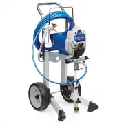
Hi-Boy Sprayers Parts 334659A 33 Hi-Boy Sprayers Parts 59 47 23 12 56 46 36 63 53 69 74 68 67 ti25461a 65 54 54a 54c 54b 7 1 2 4 1 2 2 2 1 Ref. Torque 140-160 in-lb (15.8 - 18.1 N•m) 30-35 in-lb (3.4 - 4.0 N•m) 23-27 in-lb (2.6 - 3.1 N•m) 1 2 4 See page 36
Page 35 - Parts List
Hi-Boy Sprayers Parts 334659A 35 Hi-Boy Sprayers Parts List Ref. Part Description Qty. 7 115498 SCREW, mch, slot/hex, wash hd 1 12 117501 SCREW, mach, slot hex wash hd 4 14 103413 PACKING, O-ring 1 22 17C540 COVER, front 1 23 255165 SHIELD, motor includes 48, 62, 65 1 25 180131 BEARING, thrust 1 27 ...
Page 36 - Control Box and Filter
Control Box and Filter 36 334659A Control Box and Filter 146 150 15 24 24 36 35 27 17 18 16 2 49 56 12 12 97 21 38 153 51 4 5 26 ti25463a 154 155 8 7 1 1 2 Ref. Torque 140-160 in-lb (15.8 - 18.1 N•m) 30-35 in-lb (3.4 - 4.0 N•m) 130-150 in-lb (14.7 - 16.9 N•m) 48-72 in-lb (5.4 - 8.1 N•m) 1 2 7 8
Page 37 - Control and Filter Parts List
Control Box and Filter 334659A 37 Control and Filter Parts List Ref. Part Description Qty. 2 104361 PACKING, o-ring 1 4 111600 PIN, grooved 1 5 277364 GASKET, seat, valve 1 12 117501 SCREW, mach, hex washer hd 3 15 17C592 MANIFOLD, fluid 1 16 FILTER, fluid 1 243080 60 mesh, original 243081 100 mesh ...
Page 38 - Wiring Diagram
Wiring Diagram 38 334659A Wiring Diagram Red (+) Black (-) PressureControlAssembly PowerPlug White Green Black from Motor 2 x Yellow ON/OFFSwitch ti5643a Capacitor Replaceable Fuse ti5643a
Page 39 - Technical Specifications
Technical Specifications 334659A 39 Technical Specifications 17D163, 17C305 US Metric SprayerMaximum fluid working pressure 3000 psi 207 bar, 20.7 MPa Maximum Delivery 0.47 gpm 2.1 lpm Maximum Tip Size 0.021 0.021 Fluid Outlet npsm 1/4 in. 1/4 in. Cycles 700 per gallon 185 per liter Generator Minimu...
Page 40 - Graco Standard Warranty
Graco Standard Warranty 40 334659A Graco Standard Warranty Graco warrants all equipment referenced in this document which is manufactured by Graco and bearing its name to be free from defects in material and workmanship on the date of sale to the original purchaser for use. With the exception of any...
Page 41 - Graco Information
All written and visual data contained in this document reflects the latest product information available at the time of publication. Graco reserves the right to make changes at any time without notice. Original instructions. This manual contains English. MM 334659 Graco Headquarters: Minneapolis Int...