Page 2 - Motherboard
Motherboard GA-880GA-UD3H Jun. 7, 2010 Jun. 7, 2010 M oth erb oa rd GA-880GA-UD3H
Page 4 - Table of Contents
- 4 - Table of Contents Box Contents ...................................................................................................................6Optional Items .................................................................................................................6GA-880GA-UD3H Moth...
Page 6 - Box Contents; Motherboard driver disk; Optional Items
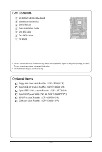
- 6 - Box Contents GA-880GA-UD3H motherboard Motherboard driver disk User's Manual Quick Installation Guide One IDE cable Two SATA cables I/O Shield Optional Items Floppy disk drive cable (Part No. 12CF1-1FD001-7*R) 2-port USB 2.0 bracket (Part No. 12CR1-1UB030-5*R) 2-port IEEE 1394a bracket (Part N...
Page 9 - Hardware Installation; -1 Installation Precautions; electrostatic shielding container.; Chapter 1 Hardware Installation
- 9 - Hardware Installation 1-1 Installation Precautions The motherboard contains numerous delicate electronic circuits and components which can become damaged as a result of electrostatic discharge (ESD). Prior to installation, carefully read the user's manual and follow these procedures: • Prior t...
Page 10 - -2 Product Specifications
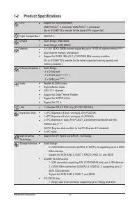
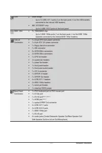
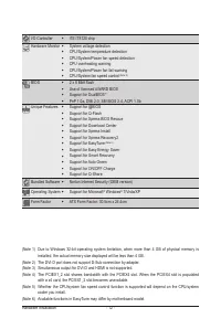
Hardware Installation - 10 - 1-2 Product Specifications CPU Support for AM3 processors: AMD Phenom ™ II processor/ AMD Athlon ™ II processor/ (Go to GIGABYTE's website for the latest CPU support list.) Hyper Transport Bus 5200 MT/s Chipset North Bridge: AMD 880G South Bridge: AMD SB850 Memor...
Page 13 - -3 Installing the CPU and CPU Cooler; Read the following guidelines before you begin to install the CPU:
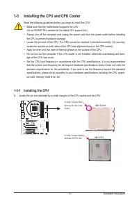
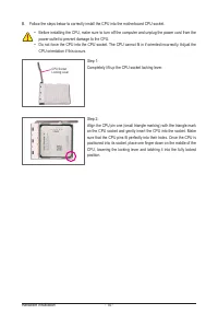
- 13 - Hardware Installation 1-3 Installing the CPU and CPU Cooler 1-3-1 Installing the CPU A. Locate the pin one (denoted by a small triangle) of the CPU socket and the CPU. Read the following guidelines before you begin to install the CPU: • Make sure that the motherboard supports the CPU. (Go to ...
Page 16 - -4 Installing the Memory; the memory to prevent hardware damage.
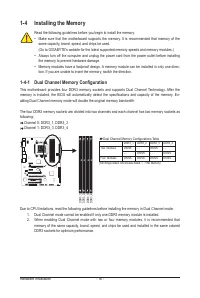
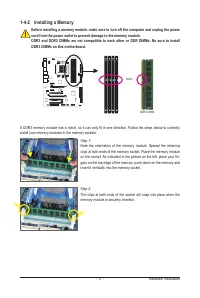
Hardware Installation - 16 - 1-4 Installing the Memory Due to CPU limitations, read the following guidelines before installing the memory in Dual Channel mode. 1. Dual Channel mode cannot be enabled if only one DDR3 memory module is installed. 2. When enabling Dual Channel mode with two or four memo...
Page 18 - -5 Installing an Expansion Card
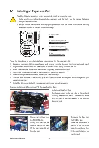
Hardware Installation - 18 - 1-5 Installing an Expansion Card Read the following guidelines before you begin to install an expansion card: • Make sure the motherboard supports the expansion card. Carefully read the manual that came with your expansion card. • Always turn off the computer and unplug ...
Page 19 - A. System Requirements
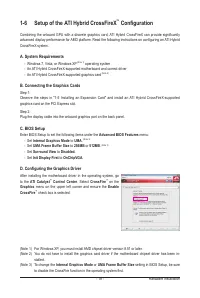
- 19 - Hardware Installation 1-6 Setup of the ATI Hybrid CrossFireX ™ Configuration Combining the onboard GPU with a discrete graphics card, ATI Hybrid CrossFireX can provide significantly advanced display performance for AMD platform. Read the following instructions on configuring an ATI Hybrid Cro...
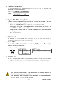
Page 20 - -7 Back Panel Connectors; Optical S/PDIF Out Connector; tions supported depend on the monitor being used.; Realtek HDMI Output; and then click; Set Default
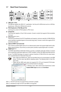
Hardware Installation - 20 - 1-7 Back Panel Connectors USB 2.0/1.1 Port The USB port supports the USB 2.0/1.1 specification. Use this port for USB devices such as a USB key-board/mouse, USB printer, USB flash drive and etc. PS/2 Keyboard or PS/2 Mouse Port Use this port to connect a PS/2 keyboard or...
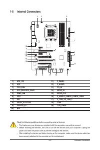
Page 23 - -8 Internal Connectors; ATX
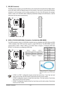
- 23 - Hardware Installation 1-8 Internal Connectors Read the following guidelines before connecting external devices: • First make sure your devices are compliant with the connectors you wish to connect. • Before installing the devices, be sure to turn off the devices and your computer. Unplug the ...
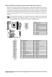
Page 27 - low level, or the CMOS values may not be accurate or may be lost.
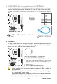
- 27 - Hardware Installation 9) GSATA2_6/7 (SATA 3Gb/s Connectors, Controlled by GIGABYTE SATA2) The SATA connectors conform to SATA 3Gb/s standard and are compatible with SATA 1.5Gb/s standard. Each SATA connector supports a single SATA device. The GIGABYTE SATA2 supports RAID 0, RAID 1 and JBOD. R...
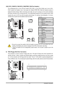
Page 28 - PW; is reading or writing data.; RES; if the computer freezes and fails to perform a normal restart.; CI
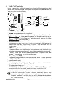
Hardware Installation - 28 - 11) F_PANEL (Front Panel Header) Connect the power switch, reset switch, speaker, chassis intrusion switch/sensor and system status indicator on the chassis to this header according to the pin assignments below. Note the positive and negative pins before connecting the c...
Page 31 - cord from the power outlet to prevent damage to the USB bracket.
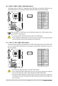
- 31 - Hardware Installation 17) F_1394_1/F_1394_2 (IEEE 1394a Headers) The headers conform to IEEE 1394a specification. The IEEE 1394a header can provide one IEEE 1394a port via an optional IEEE 1394a bracket. For purchasing the optional IEEE 1394a bracket, please con-tact the local dealer. Pin No....
Page 32 - faults
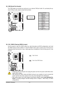
Hardware Installation - 32 - 18) COM (Serial Port Header) The COM header can provide one serial port via an optional COM port cable. For purchasing the op-tional COM port cable, please contact the local dealer. Pin No. Definition 1 NDCD- 2 NSIN 3 NSOUT 4 NDTR- 5 GND 6 NDSR- 7 NRTS- 8 NCTS- 9 NRI- 10...
Page 33 - Chapter 2 BIOS Setup
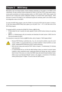
- 33 - BIOS Setup BIOS (Basic Input and Output System) records hardware parameters of the system in the CMOS on the motherboard. Its major functions include conducting the Power-On Self-Test (POST) during system startup, saving system parameters and loading operating system, etc. BIOS includes a BIO...
Page 34 - Full Screen LOGO Show
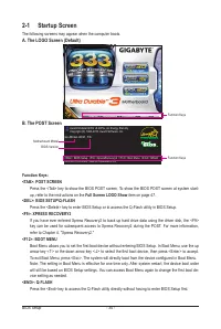
BIOS Setup - 34 - 2-1 Startup Screen The following screens may appear when the computer boots. A. The LOGO Screen (Default) B. The POST Screen Motherboard Model BIOS Version Award Modular BIOS v6.00PG, An Energy Star Ally Copyright (C) 1984-2010, Award Software, Inc. GA-880GA-UD3H F3b . . . . <DE...
Page 35 - BIOS Setup Program Function Keys; Load Optimized Defaults
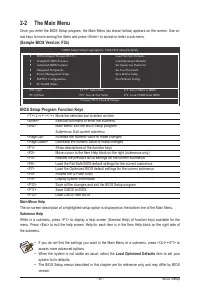
- 35 - BIOS Setup 2-2 The Main Menu Once you enter the BIOS Setup program, the Main Menu (as shown below) appears on the screen. Use ar-row keys to move among the items and press <Enter> to accept or enter a sub-menu. (Sample BIOS Version: F3b) Main Menu Help The on-screen description of a hig...
Page 36 - BIOS Setup; F11: Save CMOS to BIOS; Use this menu to configure all the power-saving functions.; Use this menu to configure the system’s PCI & PnP resources.
BIOS Setup - 36 - The Functions of the <F11> and <F12> keys (For the Main Menu Only) F11: Save CMOS to BIOS This function allows you to save the current BIOS settings to a profile. You can create up to 8 profiles (Profile 1-8) and name each profile. First enter the profile name (to e...
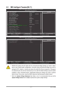
Page 37 - System Voltage Optimized; item blinks in red, it is recommended that you set the; System Voltage Control; item to; Auto; to optimize the system voltage settings.
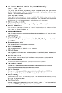
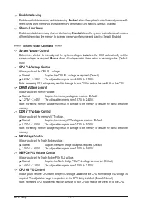
- 37 - BIOS Setup 2-3 MB Intelligent Tweaker(M.I.T.) • Whether the system will work stably with the overclock/overvoltage settings you made is depen- dent on your overall system configurations. Incorrectly doing overclock/overvoltage may result in damage to CPU, chipset, or memory and reduce the use...
Page 38 - IGX Configuration; Init Display First; Onboard VGA output connect; VGA Core Clock control
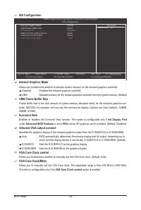
BIOS Setup - 38 - CMOS Setup Utility-Copyright (C) 1984-2010 Award Software IGX Configuration higf : Move Enter: Select +/-/PU/PD: Value F10: Save ESC: Exit F1: General Help F5: Previous Values F6: Fail-Safe Defaults F7: Optimized Defaults Item Help Menu Level Internal Graphics Mode [UMA] UMA Fra...
Page 40 - Manual; RAS to CAS R/W Delay
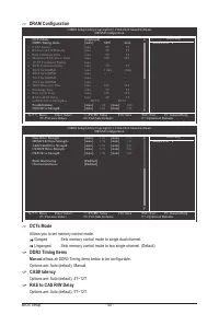
BIOS Setup - 40 - DCTs Mode Allows you to set memory control mode. Ganged Sets memory control mode to single dual-channel. Unganged Sets memory control mode to two single-channel. (Default) DDR3 Timing Items Manual allows all DDR3 Timing items below to be configurable. Options are: Auto (default), M...
Page 41 - DQS Drive Strength
- 41 - BIOS Setup Row Precharge Time Options are: Auto (default), 5T~12T. Minimum RAS Active Time Options are: Auto (default), 15T~30T. 1T/2T Command Timing Options are: Auto (default), 1T, 2T. TwTr Command Delay Options are: Auto (default), 4T~7T. Trfc0 for DIMM1 Options are: Auto (default), 90ns, ...
Page 43 - CPU Voltage Control; Allows you to set the CPU voltage.; sets the CPU voltage as required. The adjustable range is de-; Normal CPU Vcore; Displays the normal operating voltage of your CPU.
- 43 - BIOS Setup CPU Voltage Control Allows you to set the CPU voltage. Auto sets the CPU voltage as required. The adjustable range is de- pendent on the CPU being installed. (Default: Normal) Note: Increasing CPU voltage may result in damage to your CPU or reduce the useful life of the CPU. Normal...
Page 44 - -4 Standard CMOS Features
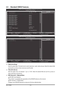
BIOS Setup - 44 - Date (mm:dd:yy) Sets the system date. The date format is week (read-only), month, date and year. Select the desired field and use the up arrow or down arrow key to set the date. Time (hh:mm:ss) Sets the system time. For example, 1 p.m. is 13:0:0. Select the desired field and use th...
Page 45 - Drive A; None; Floppy 3 Mode Support
- 45 - BIOS Setup • Auto Lets the BIOS automatically detect IDE/SATA devices during the POST. (Default) • None If no IDE/SATA devices are used, set this item to None so the system will skip the detection of the device during the POST for faster system startup. Access Mode Sets the hard drive access ...
Page 46 - -5 Advanced BIOS Features; MB Intelligent; AMD C1E Support
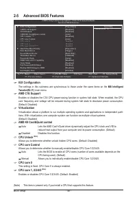
BIOS Setup - 46 - 2-5 Advanced BIOS Features IGX Configuration The settings in this submenu are synchronous to those under the same items on the MB Intelligent Tweaker(M.I.T.) main menu. AMD C1E Support Enables or disables the C1E CPU power-saving function in system halt state. When enabled, the CPU...
Page 48 - -6 Integrated Peripherals
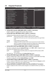
BIOS Setup - 48 - 2-6 Integrated Peripherals OnChip SATA Controller (AMD SB850, SATA3_0~SATA3_5 connectors) Enables or disables the integrated SATA controller. (Default: Enabled) OnChip SATA Type (AMD SB850, SATA3_0~SATA3_3 connectors) Configures the operating mode of the integrated SATA3_0~SATA3_3 ...
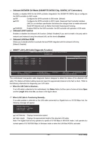
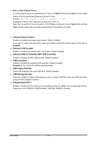
Page 49 - Onboard LAN Function; Disabled; Onboard LAN Boot ROM; Status; SMART LAN (LAN Cable Diagnostic Function)
- 49 - BIOS Setup Onboard SATA/IDE Ctrl Mode (GIGABYTE SATA2 Chip, GSATA2_6/7 Connectors) Enables or disables RAID for the SATA controller integrated in the GIGABYTE SATA2 chip or configures the SATA controller to AHCI mode. IDE Configures the SATA controller to IDE mode. (Default) AHCI Configures t...
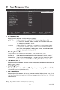
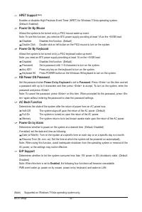
Page 51 - ACPI Suspend Type; Specifies the ACPI sleep state when the system enters suspend.; Soft-Off by Power button; -7 Power Management Setup
- 51 - BIOS Setup ACPI Suspend Type Specifies the ACPI sleep state when the system enters suspend. S1(POS) Enables the system to enter the ACPI S1 (Power on Suspend) sleep state. In S1 sleep state, the system appears suspended and stays in a low power mode. The system can be resumed at any time. S3(...
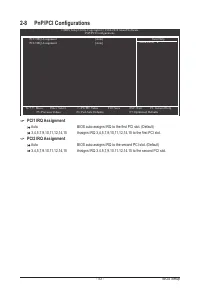
Page 53 - PCI1 IRQ Assignment; PCI2 IRQ Assignment
- 53 - BIOS Setup PCI1 IRQ Assignment Auto BIOS auto-assigns IRQ to the first PCI slot. (Default) 3,4,5,7,9,10,11,12,14,15 Assigns IRQ 3,4,5,7,9,10,11,12,14,15 to the first PCI slot. PCI2 IRQ Assignment Auto BIOS auto-assigns IRQ to the second PCI slot. (Default) 3,4,5,7,9,10,11,12,14,15 Assigns IRQ...
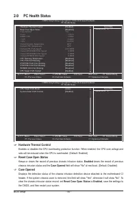
Page 54 - Enabled; Case Opened; Reset Case Open Status; -9 PC Health Status
BIOS Setup - 54 - Hardware Thermal Control Enables or disables the CPU overheating protection function. When enabled, the CPU core voltage and ratio will be reduced when the CPU is overheated. (Default: Enabled) Reset Case Open Status Keeps or clears the record of previous chassis intrusion status. ...
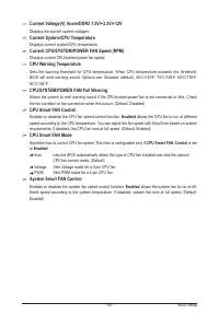
Page 55 - CPU Smart FAN Mode; CPU Smart FAN Control; System Smart FAN Control
- 55 - BIOS Setup Current Voltage(V) Vcore/DDR3 1.5V/+3.3V/+12V Displays the current system voltages. Current System/CPU Temperature Displays current system/CPU temperature. Current CPU/SYSTEM/POWER FAN Speed (RPM) Displays current CPU/system/power fan speed. CPU Warning Temperature Sets the warning...
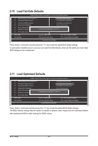
Page 56 - -11 Load Optimized Defaults
BIOS Setup - 56 - Press <Enter> on this item and then press the <Y> key to load the safest BIOS default settings. In case system instability occurs, you may try to load Fail-Safe defaults, which are the safest and most stable BIOS settings for the motherboard. 2-10 Load Fail-Safe Default...
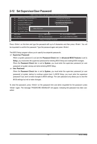
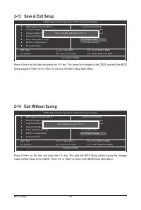
Page 58 - -14 Exit Without Saving
BIOS Setup - 58 - Press <Enter> on this item and press the <Y> key. This saves the changes to the CMOS and exits the BIOS Setup program. Press <N> or <Esc> to return to the BIOS Setup Main Menu. 2-13 Save & Exit Setup Press <Enter> on this item and press the <Y&g...
Page 59 - -1 Installing Chipset Drivers; Chapter 3 Drivers Installation
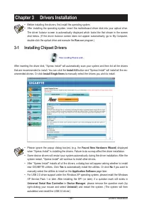
- 59 - Drivers Installation 3-1 Installing Chipset Drivers Chapter 3 Drivers Installation After inserting the driver disk, "Xpress Install" will automatically scan your system and then list all the drivers that are recommended to install. You can click the Install All button and "Xpress ...
Page 60 - Drivers Installation; -2 Application Software; Install; button on the right of an item to install it.; -3 Technical Manuals
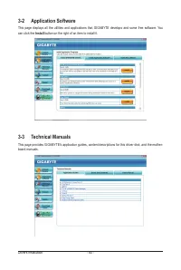
Drivers Installation - 60 - 3-2 Application Software This page displays all the utilities and applications that GIGABYTE develops and some free software. You can click the Install button on the right of an item to install it. 3-3 Technical Manuals This page provides GIGABYTE's application guides, co...
Page 62 - Download Center; button to link to the GIGABYTE
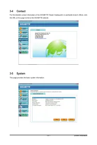
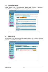
Drivers Installation - 62 - 3-6 Download Center To update the BIOS, drivers, or applications, click the Download Center button to link to the GIGABYTE website. The latest version of the BIOS, drivers, or applications will be displayed. 3-7 New Utilities This page provides a quick link to GIGABYTE's ...
Page 63 - -1 Xpress Recovery2; Chapter 4 Unique Features; Installation and Configuration:; A. Installing Windows Vista and Partitioning the Hard Drive
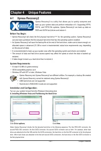
- 63 - Unique Features 4-1 Xpress Recovery2 Chapter 4 Unique Features Xpress Recovery2 is a utility that allows you to quickly compress and back up your system data and perform restoration of it. Supporting NTFS, FAT32, and FAT16 file systems, Xpress Recovery2 can back up data on PATA and SATA hard ...
Page 64 - Press any key to startup Xpress Recovery2
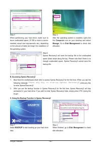
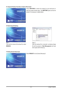
Unique Features - 64 - Step 3:When partitioning your hard drive, make sure to leave unallocated space (10 GB or more is recom-mended; actual size requirements vary, depending on the amount of data) and begin the installation of the operating system. Step 1:Select BACKUP to start backing up your hard...
Page 66 - Unique Features; -2 BIOS Update Utilities; design, which enhances protection for the; What is DualBIOS; site and update the BIOS.
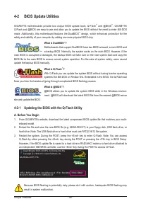
Unique Features - 66 - 4-2 BIOS Update Utilities GIGABYTE motherboards provide two unique BIOS update tools, Q-Flash ™ and @BIOS ™ . GIGABYTE Q-Flash and @BIOS are easy-to-use and allow you to update the BIOS without the need to enter MS-DOS mode. Additionally, this motherboard features the DualBIOS...
Page 67 - Update BIOS from Drive; The; Save Main BIOS to Drive; option allows you to save the current BIOS file.; Make sure the BIOS update file matches your motherboard model.
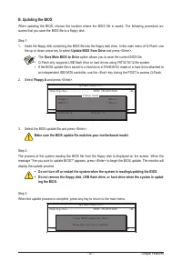
- 67 - Unique Features B. Updating the BIOS When updating the BIOS, choose the location where the BIOS file is saved. The following procedure as-sumes that you save the BIOS file to a floppy disk. Step 1: 1. Insert the floppy disk containing the BIOS file into the floppy disk drive. In the main menu...
Page 68 - Load Optimized Defaults; dure is complete after the system restarts.
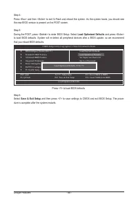
Unique Features - 68 - Step 4:Press <Esc> and then <Enter> to exit Q-Flash and reboot the system. As the system boots, you should see the new BIOS version is present on the POST screen. Step 5:During the POST, press <Delete> to enter BIOS Setup. Select Load Optimized Defaults and p...
Page 69 - C. After Updating the BIOS
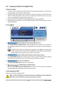
- 69 - Unique Features 4-2-2 Updating the BIOS with the @BIOS Utility A. Before You Begin 1. In Windows, close all applications and TSR (Terminate and Stay Resident) programs. This helps prevent unexpected failures when performing a BIOS update. 2. During the BIOS update process, ensure the Internet...
Page 70 - The EasyTune 6 Interface; Tab
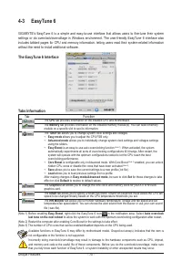
Unique Features - 70 - 4-3 EasyTune 6 GIGABYTE's EasyTune 6 is a simple and easy-to-use interface that allows users to fine-tune their system settings or do overclock/overvoltage in Windows environment. The user-friendly EasyTune 6 interface also includes tabbed pages for CPU and memory information,...
Page 71 - -4 Easy Energy Saver; Meter Mode - Button Information Table
- 71 - Unique Features 4-4 Easy Energy Saver GIGABYTE Easy Energy Saver is a revolutionary technology that delivers unparalleled power savings with a click of the button. Featuring an advanced proprietary software design, GIGABYTE Easy Energy Saver is able to provide exceptional power savings and en...
Page 72 - Total Mode - Button Information Table
Unique Features - 72 - C. Stealth Mode In Stealth Mode, the system continues to work with the user-defined power saving settings, even after the system is restarted. Re-enter the application only if you want to make any changes or completely close the application. (Note 1) Maximize system power savi...
Page 73 - Directions for using Q-Share; Options Descriptions
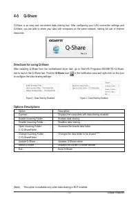
- 73 - Unique Features 4-5 Q-Share Q-Share is an easy and convenient data sharing tool. After configuring your LAN connection settings and Q-Share, you are able to share your data with computers on the same network, making full use of Internet resources. Directions for using Q-Share After installing...
Page 74 - Config
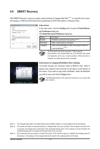
Unique Features - 74 - 4-6 SMART Recovery With SMART Recovery, users can quickly create backups of changed data files (Note 1) or copy files from a spe- cific backup on PATA and SATA hard drives (partitioned on NTFS file system) in Windows Vista. Instructions for copying files/folders from a backup:...
Page 75 - Selecting a system energy saving mode; Con
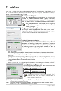
- 75 - Unique Features 4-7 Auto Green Auto Green is an easy-to-use tool that provides users with simple options to enable system power savings via a Bluetooth cell phone. When the phone is out of the range of the computer's Bluetooth receiver, the sys- tem will enter the specified power saving mode....
Page 77 - Appendix; Chapter 5 Appendix; and operating system.; Before you begin; An empty formatted floppy disk.; -1-1 Configuring AMD SB850 SATA Controller
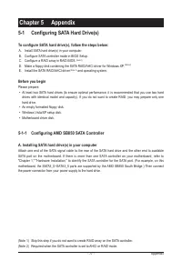
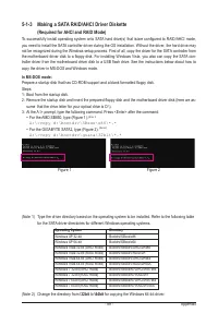
- 77 - Appendix Chapter 5 Appendix 5-1 Configuring SATA Hard Drive(s) To configure SATA hard drive(s), follow the steps below: A. Install SATA hard drive(s) in your computer. B. Configure SATA controller mode in BIOS Setup. C. Configure a RAID array in RAID BIOS. (Note 1) D. Make a floppy disk conta...
Page 78 - B. Configuring SATA controller mode in BIOS Setup
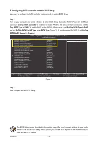
Appendix - 78 - The BIOS Setup menus described in this section may differ from the exact settings for your moth-erboard. The actual BIOS Setup menu options you will see shall depend on the motherboard you have and the BIOS version. B. Configuring SATA controller mode in BIOS Setup Make sure to confi...
Page 79 - C. Configuring RAID set in RAID BIOS; Main Menu; Figure 3
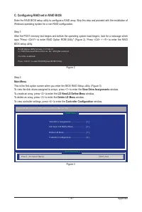
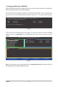
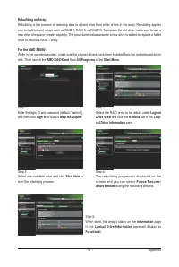
- 79 - Appendix C. Configuring RAID set in RAID BIOS Enter the RAID BIOS setup utility to configure a RAID array. Skip this step and proceed with the installation of Windows operating system for a non-RAID configuration. Step 1: After the POST memory test begins and before the operating system boot ...
Page 80 - Create Arrays Manually; In the; LD Define Menu; Figure 4
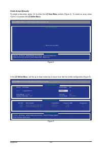
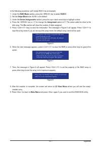
Appendix - 80 - Create Arrays Manually To create a new array, press <2> to enter the LD View Menu window (Figure 4). To create an array, press <Ctrl+C> to access the LD Define Menu . In the LD Define Menu , use the up or down arrow key to move to an item for further configuration (Figure...
Page 82 - View LD Defination Menu
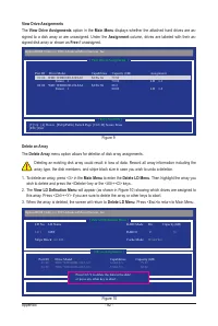
Appendix - 82 - Delete an Array The Delete Array menu option allows for deletion of disk array assignments. Deleting an existing disk array could result in loss of data. Record all array information including the array type, the disk members, and stripe block size in case you wish to undo a deletion...
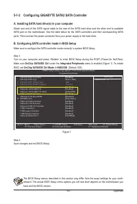
Page 83 - -1-2 Configuring GIGABYTE SATA2 SATA Controller; under the; to
- 83 - Appendix The BIOS Setup menus described in this section may differ from the exact settings for your moth-erboard. The actual BIOS Setup menu options you will see shall depend on the motherboard you have and the BIOS version. Figure 1 Step 2: Save changes and exit BIOS Setup. 5-1-2 Configuring...
Page 84 - C. Configuring a RAID array in RAID BIOS; Main Menu
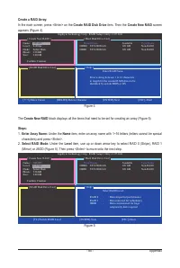
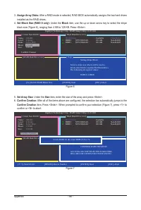
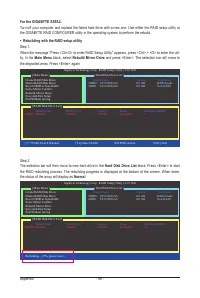
Appendix - 84 - C. Configuring a RAID array in RAID BIOS Enter the RAID BIOS setup utility to configure a RAID array. Skip this step and proceed to the installation of Windows operating system for a non-RAID configuration. After the POST memory test begins and before the operating system boot begins...
Page 87 - RAID Disk Drive List
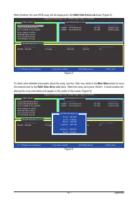
- 87 - Appendix When finished, the new RAID array will be displayed in the RAID Disk Drive List block (Figure 8). Figure 8 Model Name RAID Level Capacity Status Members(HDDx) RDD0: GRAID 0-Stripe 240 GB Normal 01 [ fg TAB]-Switch Window [ hi ]-Select ITEM [ENTER]-Action [ESC]-Exit [ RAID Disk Drive ...
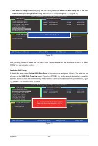
Page 88 - After configuring the RAID array, select the; Save And Exit Setup; item in the main; Delete the RAID Array:; To delete the array, select; Delete RAID Disk Drive; will move to the
Appendix - 88 - Model Name RAID Level Capacity Status Members(HDDx) RDD0: GRAID 0-Stripe 240 GB Normal 01 [ fg TAB]-Switch Window [ hi ]-Select ITEM [ENTER]-Action [ESC]-Exit [ RAID Disk Drive List ] [ Main Menu ] [ Hard Disk Drive List ] Gigabyte Technology Corp. RAID Setup Utility v1.07.16G Create...
Page 91 - -1-4 Installing the SATA RAID/AHCI Driver and Operating System; A. Installing Windows XP; to Figure 2 below will appear. Select; and press; Figure 1
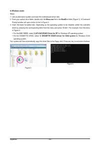
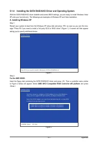
- 91 - Appendix 5-1-4 Installing the SATA RAID/AHCI Driver and Operating System With the SATA RAID/AHCI driver diskette and correct BIOS settings, you are ready to install Windows Vista/XP onto your hard drive(s). The followings are examples of Windows XP and Vista installation. A. Installing Window...
Page 92 - For the GIGABYTE SATA2:; to Figure 3 below will appear. Select; RAID/AHCI Driver for GIGABYTE GBB36X Controller; and press
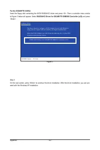
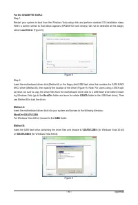
Appendix - 92 - For the GIGABYTE SATA2: Insert the floppy disk containing the SATA RAID/AHCI driver and press <S>. Then a controller menu similar to Figure 3 below will appear. Select RAID/AHCI Driver for GIGABYTE GBB36X Controller (x32) and press <Enter>. Step 3: On the next screen, pre...
Page 93 - B. Installing Windows Vista; Load; folder and save the whole; SBxxxV; folder to; LH
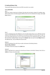
- 93 - Appendix B. Installing Windows Vista The procedure below assumes that only one RAID array exists in your system. For the AMD SB850: Step 1: Restart your system to boot from the Windows Vista setup disk and perform standard OS installation steps. When a screen similar to that below appears (RA...
Page 94 - AMD AHCI Compatible RAID Controller; and click; Next; to continue
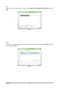
Appendix - 94 - Step 3: When a screen as shown in Figure 6 appears, select AMD AHCI Compatible RAID Controller and click Next . Step 4: After the driver is loaded, the RAID drive will appear. Select the RAID drive and then click Next to continue the OS installation (Figure 7). Figure 6 Figure 7
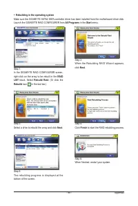
Page 96 - GIGABYTE GBB36X Controller; and click
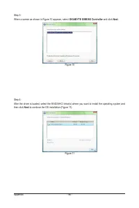
Appendix - 96 - Step 3: When a screen as shown in Figure 10 appears, select GIGABYTE GBB36X Controller and click Next . Step 4:After the driver is loaded, select the RAID/AHCI drive(s) where you want to install the operating system and then click Next to continue the OS installation (Figure 11). Fig...
Page 100 - -2 Configuring Audio Input and Output; A. Configuring Speakers; HD Audio Manager
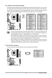
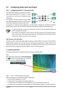
Appendix - 100 - 5-2-1 Configuring 2/4/5.1/7.1-Channel Audio The motherboard provides six audio jacks on the back panel which support 2/4/5.1/7.1-channel (Note) audio. The picture to the right shows the default audio jack assignments. The integrated HD (High Definition) audio provides jack retasking...
Page 101 - B. Configuring Sound Effect
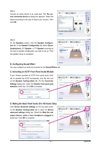
- 101 - Appendix Step 2:Connect an audio device to an audio jack. The The cur- rent connected device is dialog box appears. Select the device according to the type of device you connect. Then click OK . Step 3:On the Speakers screen, click the Speaker Configura - tion tab. In the Speaker Configurati...
Page 102 - Digital Input; tab to select the default format. Click; OK
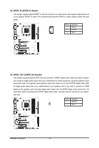
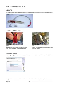
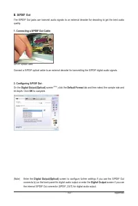
Appendix - 102 - 5-2-2 Configuring S/PDIF In/Out A. S/PDIF In The S/PDIF In cable (optional) allows you to input digital audio signals to the computer for audio processing. 1. Installing the S/PDIF In Cable: 2. Configuring S/PDIF In: On the Digital Input screen, click the Default Format tab to selec...
Page 104 - -2-3 Enabling the Dolby Home Theater Function; Dolby GUI Software
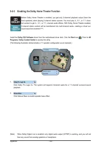
Appendix - 104 - 5-2-3 Enabling the Dolby Home Theater Function Before Dolby Home Theater is enabled, you get only 2-channel playback output (from the front speakers) when playing 2-channel stereo sources. You must play 4-, 5.1-, or 7.1- chan-nel content to get 4-, 5.1-, or 7.1- channel audio effect...
Page 105 - and select; Set Default Device
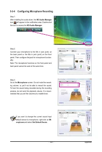
- 105 - Appendix 5-2-4 Configuring Microphone Recording Step 1:After installing the audio driver, the HD Audio Manager icon will appear in the notification area. Double-click the icon to access the HD Audio Manager . Step 2:Connect your microphone to the Mic in jack (pink) on the back panel or the M...
Page 106 - * Enabling Stereo Mix
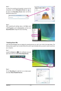
Appendix - 106 - Step 5:After completing the settings above, click Start , point to All Programs , point to Accessories , and then click Sound Recorder to begin the sound recording. Step 1:Locate the Volume icon in the notification area and right-click on this icon. Select Recording Devices . Step 2...
Page 107 - B. Playing the Recorded Sound
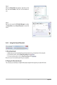
- 107 - Appendix Step 3:When the Stereo Mix item appears, right-click on this item and select Enable . Then set it as the default de- vice. Step 4:Now you can access the HD Audio Manager to config- ure Stereo Mix and use Sound Recorder to record the sound. 5-2-5 Using the Sound Recorder A. Recording...
Page 111 - -4 Regulatory Statements; Regulatory Notices; collected separately, and disposed of properly.; WEEE Symbol Statement; the product for details of environmentally safe recycling.
- 111 - Appendix 5-4 Regulatory Statements Regulatory Notices This document must not be copied without our written permission, and the contents there of must not be imparted to a third party nor be used for any unauthorized purpose. Contravention will be prosecuted. We believe that the information c...
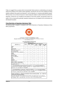
Page 112 - China Restriction of Hazardous Substances Table
Appendix - 112 - Finally, we suggest that you practice other environmentally friendly actions by understanding and using the energy-saving features of this product (where applicable), recycling the inner and outer packaging (including shipping containers) this product was delivered in, and by dispos...
Page 115 - Contact Us
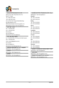
- 115 - Appendix Contact Us • GIGA-BYTE TECHNOLOGY CO., LTD. Address: No.6, Bau Chiang Road, Hsin-Tien, Taipei 231, Taiwan TEL: +886-2-8912-4000 FAX: +886-2-8912-4003Tech. and Non-Tech. Support (Sales/Marketing) :http://ggts.gigabyte.com.twWEB address (English): http://www.gigabyte.comWEB address (C...
Page 116 - GIGABYTE Global Service System
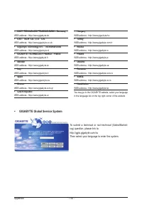
Appendix - 116 - • G.B.T. TECHNOLOGY TRADING GMBH - Germany WEB address : http://www.gigabyte.de • G.B.T. TECH. CO., LTD. - U.K. WEB address : http://www.giga-byte.co.uk • Giga-Byte Technology B.V. - The Netherlands WEB address : http://www.giga-byte.nl • GIGABYTE TECHNOLOGY FRANCE - France WEB addr...


 Gigabyte B650
User Manual
Gigabyte B650
User Manual
 Gigabyte GA 770T D3L rev 1 x
User Manual
Gigabyte GA 770T D3L rev 1 x
User Manual
 Gigabyte GA 770T D3L rev 3 1
User Manual
Gigabyte GA 770T D3L rev 3 1
User Manual
 Gigabyte GA 870A UD3 rev 2 2
User Manual
Gigabyte GA 870A UD3 rev 2 2
User Manual
 Gigabyte GA 8I848P rev 1 x
User Manual
Gigabyte GA 8I848P rev 1 x
User Manual
 Gigabyte GA 8I848P rev 2 x
User Manual
Gigabyte GA 8I848P rev 2 x
User Manual
 Gigabyte GA 8IG1000 rev 1 x
User Manual
Gigabyte GA 8IG1000 rev 1 x
User Manual
 Gigabyte GA 8IG1000 rev 3 x
User Manual
Gigabyte GA 8IG1000 rev 3 x
User Manual
 Gigabyte GA 8IG1000 Pro rev 2 x
User Manual
Gigabyte GA 8IG1000 Pro rev 2 x
User Manual
 Gigabyte GA 8IPE1000 rev 1 x
User Manual
Gigabyte GA 8IPE1000 rev 1 x
User Manual
 Gigabyte GA 8IPE1000 rev 3 x
User Manual
Gigabyte GA 8IPE1000 rev 3 x
User Manual
 Gigabyte GA EX58 DS4 rev 1 0
User Manual
Gigabyte GA EX58 DS4 rev 1 0
User Manual
 Gigabyte GA EX58 UD3R rev 1 6
User Manual
Gigabyte GA EX58 UD3R rev 1 6
User Manual
 Gigabyte GA EX58 UD3R rev 1 7
User Manual
Gigabyte GA EX58 UD3R rev 1 7
User Manual
 Gigabyte GA EX58 UD3R SLI rev 1 0
User Manual
Gigabyte GA EX58 UD3R SLI rev 1 0
User Manual
 Gigabyte GA EX58 UD4 rev 1 0
User Manual
Gigabyte GA EX58 UD4 rev 1 0
User Manual
 Gigabyte GA EX58 UD5P rev 1 0
User Manual
Gigabyte GA EX58 UD5P rev 1 0
User Manual
 Gigabyte GA GC330UD rev 1 0
User Manual
Gigabyte GA GC330UD rev 1 0
User Manual
 Gigabyte GA H55 UD3H rev 1 0
User Manual
Gigabyte GA H55 UD3H rev 1 0
User Manual
 Gigabyte GA H55 UD3H rev 1 3
User Manual
Gigabyte GA H55 UD3H rev 1 3
User Manual