Page 2 - Motherboard
Motherboard GA-770T -D3L Jul 26, 2010 Jul. 26, 2010 M oth erb oa rd GA-770T -D3L
Page 4 - Table of Contents; -2 Product Specifications
- 4 - Table of Contents Box Contents ...................................................................................................................6Optional Items .................................................................................................................6GA-770T-D3L Mother...
Page 5 - -1-1 Configuring the Onboard SATA Controller; -2 Configuring Audio Input and Output
- 5 - Chapter 3 Drivers Installation ........................................................................................55 3-1 Installing Chipset Drivers ............................................................................... 553-2 Application Software .....................................
Page 6 - Box Contents; Motherboard driver disk; Optional Items
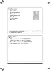
- 6 - Box Contents GA-770T-D3L motherboard Motherboard driver disk User's Manual Quick Installation Guide One IDE cable Two SATA cables I/O Shield Optional Items Floppy disk drive cable (Part No. 12CF1-1FD001-7*R) 2-port USB 2.0 bracket (Part No. 12CR1-1UB030-5*R) 2-port SATA power cable (Part No. 1...
Page 9 - Hardware Installation; -1 Installation Precautions; electrostatic shielding container.; Chapter 1 Hardware Installation
- 9 - Hardware Installation 1-1 Installation Precautions The motherboard contains numerous delicate electronic circuits and components which can become damaged as a result of electrostatic discharge (ESD). Prior to installation, carefully read the user's manual and follow these procedures: • Prior t...
Page 10 - High Definition Audio
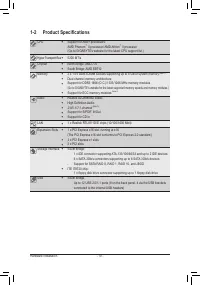
Hardware Installation - 10 - 1-2 Product Specifications CPU Support for AM3+ processors: AMD Phenom ™ II processor/ AMD Athlon ™ II processor (Go to GIGABYTE's website for the latest CPU support list.) Hyper Transport Bus 5200 MT/s Chipset North Bridge: AMD 770 South Bridge: AMD SB710 Memory...
Page 11 - x floppy disk drive connector
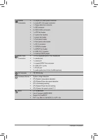
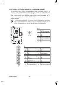
- 11 - Hardware Installation Internal 1 x 24-pin ATX main power connector Connectors 1 x 4-pin ATX 12V power connector 1 x floppy disk drive connector 1 x IDE connector 6 x SATA 3Gb/s connectors 1 x CPU fan header 2 x system fan headers 1 x power fan header 1 x front panel header ...
Page 13 - -3 Installing the CPU and CPU Cooler; Read the following guidelines before you begin to install the CPU:
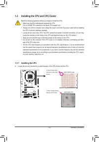
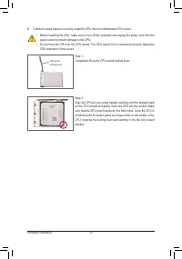
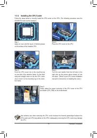
- 13 - Hardware Installation 1-3 Installing the CPU and CPU Cooler 1-3-1 Installing the CPU A. Locate the pin one (denoted by a small triangle) of the CPU socket and the CPU. Read the following guidelines before you begin to install the CPU: • Make sure that the motherboard supports the CPU. (Go to ...
Page 16 - -4 Installing the Memory; the memory to prevent hardware damage.
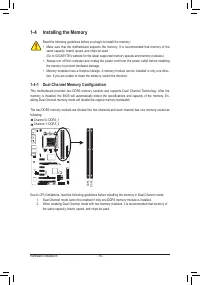
Hardware Installation - 16 - 1-4 Installing the Memory Due to CPU limitations, read the following guidelines before installing the memory in Dual Channel mode. 1. Dual Channel mode cannot be enabled if only one DDR3 memory module is installed. 2. When enabling Dual Channel mode with two memory modul...
Page 17 - install your memory modules in the memory sockets.
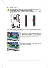
- 17 - Hardware Installation Notch 1-4-2 Installing a Memory Before installing a memory module, make sure to turn off the computer and unplug the power cord from the power outlet to prevent damage to the memory module.DDR3 and DDR2 DIMMs are not compatible to each other or DDR DIMMs. Be sure to inst...
Page 18 - -5 Installing an Expansion Card
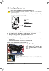
Hardware Installation - 18 - 1-5 Installing an Expansion Card Read the following guidelines before you begin to install an expansion card: • Make sure the motherboard supports the expansion card. Carefully read the manual that came with your expansion card. • Always turn off the computer and unplug ...
Page 19 - -6 Back Panel Connectors; Parallel Port; describes the states of the LAN port LEDs.
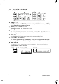
- 19 - Hardware Installation 1-6 Back Panel Connectors USB 2.0/1.1Port The USB port supports the USB 2.0/1.1 specification. Use this port for USB devices such as a USB key - board/mouse, USB printer, USB flash drive and etc. PS/2 Keyboard or PS/2 Mouse Port Use this port to connect a PS/2 keyboard o...
Page 21 - -7 Internal Connectors; ATX
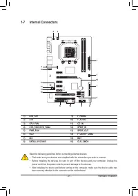
- 21 - Hardware Installation 1-7 Internal Connectors Read the following guidelines before connecting external devices: • First make sure your devices are compliant with the connectors you wish to connect. • Before installing the devices, be sure to turn off the devices and your computer. Unplug the ...
Page 25 - PW; is reading or writing data.; RES; if the computer freezes and fails to perform a normal restart.; CI
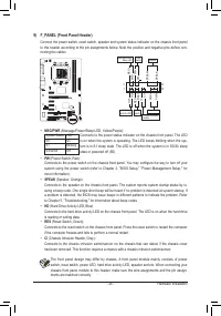
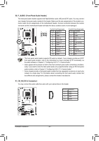
- 25 - Hardware Installation 9) F_PANEL (Front Panel Header) Connect the power switch, reset switch, speaker and system status indicator on the chassis front panel to this header according to the pin assignments below. Note the positive and negative pins before con-necting the cables. The front pane...
Page 28 - self or uncertain about the battery model.
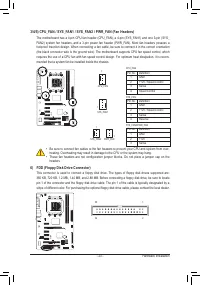
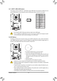
Hardware Installation - 28 - 14) F_USB1/F_USB2 (USB Headers) The headers conform to USB 2.0/1.1 specification. Each USB header can provide two USB ports via an optional USB bracket. For purchasing the optional USB bracket, please contact the local dealer. Pin No. Definition 1 Power (5V) 2 Power (5V)...
Page 29 - faults
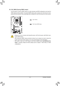
- 29 - Hardware Installation 16) CLR_CMOS (Clearing CMOS Jumper) Use this jumper to clear the CMOS values (e.g. date information and BIOS configurations) and reset the CMOS values to factory defaults. To clear the CMOS values, place a jumper cap on the two pins to tem-porarily short the two pins or ...
Page 31 - Chapter 2 BIOS Setup
- 31 - BIOS Setup BIOS (Basic Input and Output System) records hardware parameters of the system in the CMOS on the motherboard. Its major functions include conducting the Power-On Self-Test (POST) during system startup, saving system parameters and loading operating system, etc. BIOS includes a BIO...
Page 32 - Full Screen LOGO Show; vice setting as needed.
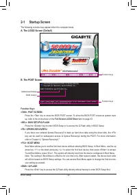
BIOS Setup - 32 - 2-1 Startup Screen The following screens may appear when the computer boots. A. The LOGO Screen (Default) B. The POST Screen Function Keys: <TAB>: POST SCREEN Press the <Tab> key to show the BIOS POST screen. To show the BIOS POST screen at system start-up, refer to the...
Page 33 - BIOS Setup Program Function Keys; Load Optimized Defaults
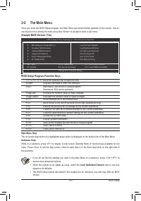
- 33 - BIOS Setup 2-2 The Main Menu Once you enter the BIOS Setup program, the Main Menu (as shown below) appears on the screen. Use ar-row keys to move among the items and press <Enter> to accept or enter a sub-menu. (Sample BIOS Version: F3a) Main Menu Help The on-screen description of a hig...
Page 34 - BIOS Setup; F11: Save CMOS to BIOS; type of errors that stop the system boot, etc.
BIOS Setup - 34 - The Functions of the <F11> and <F12> keys (For the Main Menu Only) F11: Save CMOS to BIOS This function allows you to save the current BIOS settings to a profile. You can create up to 8 profiles (Profile 1-8) and name each profile. First enter the profile name (to e...
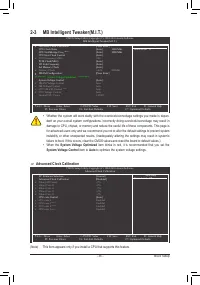
Page 35 - System Voltage Optimized; item blinks in red, it is recommended that you set the; System Voltage Control; item to; Auto; to optimize the system voltage settings.; Advanced Clock Calibration
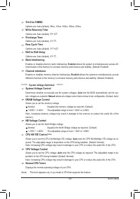
- 35 - BIOS Setup 2-3 MB Intelligent Tweaker(M.I.T.) • Whether the system will work stably with the overclock/overvoltage settings you made is depen- dent on your overall system configurations. Incorrectly doing overclock/overvoltage may result in damage to CPU, chipset, or memory and reduce the use...
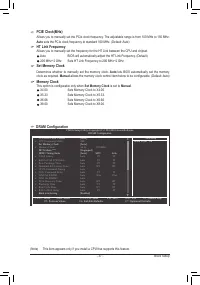
Page 37 - HT Link Frequency; Memory Clock; This option is configurable only when; Set Memory Clock
- 37 - BIOS Setup PCIE Clock(MHz) Allows you to manually set the PCIe clock frequency. The adjustable range is from 100 MHz to 150 MHz. Auto sets the PCIe clock frequency to standard 100 MHz. (Default: Auto) HT Link Frequency Allows you to manually set the frequency for the HT Link between the CPU a...
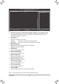
Page 38 - Allows you to set memory control mode.; Manual; allows all DDR2 Timing items below to be configurable.
BIOS Setup - 38 - (Note) This item appears only if you install a CPU that supports this feature. CMOS Setup Utility-Copyright (C) 1984-2010 Award Software MB Intelligent Tweaker(M.I.T.) higf : Move Enter: Select +/-/PU/PD: Value F10: Save ESC: Exit F1: General Help F5: Previous Values F6: Fail-Safe ...
Page 40 - -4 Standard CMOS Features
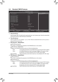
BIOS Setup - 40 - Date (mm:dd:yy) Sets the system date. The date format is week (read-only), month, date and year. Select the desired field and use the up arrow or down arrow key to set the date. Time (hh:mm:ss) Sets the system time. For example, 1 p.m. is 13:0:0. Select the desired field and use th...
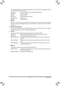
Page 41 - Drive A; None; Floppy 3 Mode Support; These fields are read-only and are determined by the BIOS POST.
- 41 - BIOS Setup The following fields display your hard drive specifications. If you wish to enter the parameters manually, refer to the information on the hard drive. Capacity Approximate capacity of the currently installed hard drive. Cylinder Number of cylinders. Head Number of heads. Precomp Wr...
Page 42 - -5 Advanced BIOS Features; AMD C1E Support; Hard Disk Boot Priority
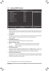
BIOS Setup - 42 - 2-5 Advanced BIOS Features AMD C1E Support (Note) Enables or disables the C1E CPU power-saving function in system halt state. When enabled, the CPU core frequency and voltage will be reduced during system halt state to decrease power consumption. (Default: Disabled) Virtualization ...
Page 43 - Password Check; Set Supervisor/User Password; item in; Away Mode; Disabled; displays; Backup BIOS Image to HDD
- 43 - BIOS Setup Password Check Specifies whether a password is required every time the system boots, or only when you enter BIOS Setup. After configuring this item, set the password(s) under the Set Supervisor/User Password item in the BIOS Main Menu. Setup A password is only required for entering...
Page 44 - -6 Integrated Peripherals; OnChip SATA Controller (AMD SB710 Chipset); AHCI; IDE; OnChip SATA Type; Onboard LAN Function; Onboard LAN Boot ROM
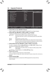
BIOS Setup - 44 - 2-6 Integrated Peripherals OnChip SATA Controller (AMD SB710 Chipset) Enables or disables the SATA controller integrated in the AMD SB710 chip. (Default: Enabled) OnChip SATA Type (AMD SB710, SATA2_0~SATA2_3 connectors) Configures the operating mode of the integrated SATA2_0~SATA2_...
Page 45 - SMART LAN (LAN Cable Diagnostic Function); fields of all four pairs of wires will show
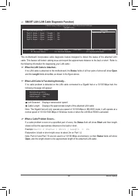
- 45 - BIOS Setup SMART LAN (LAN Cable Diagnostic Function) CMOS Setup Utility-Copyright (C) 1984-2010 Award Software SMART LAN Start detecting at Port..... Part1-2 Status = Open / Length = 0m Part3-6 Status = Open / Length = 0m Part4-5 Status = Open / Length = 0m Part7-8 Status = Open / Length = 0m...
Page 46 - will turn off all of the USB functionalities below.; Parallel Port Mode; is set to; ECP; or
BIOS Setup - 46 - Onboard Audio Function Enables or disables the onboard audio function. (Default: Enabled) If you wish to install a 3rd party add-in audio card instead of using the onboard audio, set this item to Disabled . USB Controllers Enables or disables the integrated USB controllers. (Defaul...
Page 47 - ACPI Suspend Type; Specifies the ACPI sleep state when the system enters suspend.; Soft-Off by Power button; -7 Power Management Setup
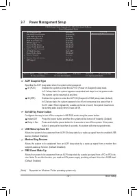
- 47 - BIOS Setup ACPI Suspend Type Specifies the ACPI sleep state when the system enters suspend. S1(POS) Enables the system to enter the ACPI S1 (Power on Suspend) sleep state. In S1 sleep state, the system appears suspended and stays in a low power mode. The system can be resumed at any time. S3(...
Page 49 - Enabled; Case Opened; Reset Case Open Status; -8 PC Health Status
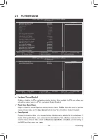
- 49 - BIOS Setup Hardware Thermal Control Enables or disables the CPU overheating protection function. When enabled, the CPU core voltage and ratio will be reduced when the CPU is overheated. (Default: Enabled) Reset Case Open Status Keeps or clears the record of previous chassis intrusion status. ...
Page 50 - CPU Smart FAN Mode; CPU Smart FAN Control; System Smart FAN Control
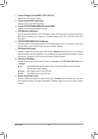
BIOS Setup - 50 - Current Voltage(V) Vcore/DDR2 1.8V/+3.3V/+12V Displays the current system voltages. Current System/CPU Temperature Displays current system/CPU temperature. Current CPU/SYSTEM/POWER FAN Speed (RPM) Displays current CPU/system/power fan speed. CPU Warning Temperature Sets the warning...
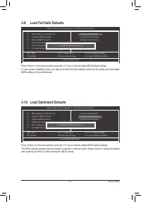
Page 51 - -10 Load Optimized Defaults
- 51 - BIOS Setup Press <Enter> on this item and then press the <Y> key to load the safest BIOS default settings. In case system instability occurs, you may try to load Fail-Safe defaults, which are the safest and most stable BIOS settings for the motherboard. 2-9 Load Fail-Safe Defaults...
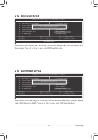
Page 53 - -13 Exit Without Saving
- 53 - BIOS Setup Press <Enter> on this item and press the <Y> key. This saves the changes to the CMOS and exits the BIOS Setup program. Press <N> or <Esc> to return to the BIOS Setup Main Menu. 2-12 Save & Exit Setup Press <Enter> on this item and press the <Y&g...
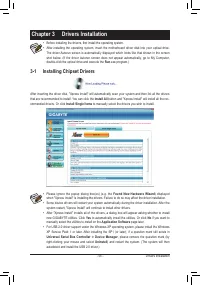
Page 55 - -1 Installing Chipset Drivers; Chapter 3 Drivers Installation
- 55 - Drivers Installation 3-1 Installing Chipset Drivers Chapter 3 Drivers Installation • Before installing the drivers, first install the operating system. • After installing the operating system, insert the motherboard driver disk into your optical drive. The driver Autorun screen is automatical...
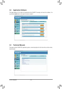
Page 56 - Drivers Installation; -2 Application Software; Install; button on the right of an item to install it.; -3 Technical Manuals
Drivers Installation - 56 - 3-2 Application Software This page displays all the utilities and applications that GIGABYTE develops and some free software. You can click the Install button on the right of an item to install it. 3-3 Technical Manuals This page provides GIGABYTE's application guides, co...
Page 58 - Download Center; button to link to the GIGABYTE
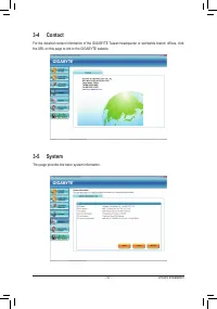
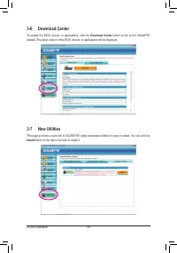
Drivers Installation - 58 - 3-6 Download Center To update the BIOS, drivers, or applications, click the Download Center button to link to the GIGABYTE website. The latest version of the BIOS, drivers, or applications will be displayed. 3-7 New Utilities This page provides a quick link to GIGABYTE's ...
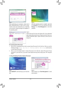
Page 59 - -1 Xpress Recovery2; Chapter 4 Unique Features; FAT32, and FAT16 file systems, Xpress Recovery2 can back up data on; Installation and Configuration:; A. Installing Windows Vista and Partitioning the Hard Drive; Drive options
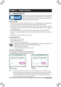
- 59 - Unique Features 4-1 Xpress Recovery2 Chapter 4 Unique Features Xpress Recovery2 is a utility that allows you to quickly compress and back up your system data and perform restoration of it. Supporting NTFS, FAT32, and FAT16 file systems, Xpress Recovery2 can back up data on PATA and SATA hard ...
Page 61 - If you wish to remove the backup file, select
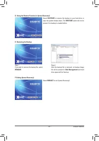
- 61 - Unique Features D. Using the Restore Function in Xpress Recovery2 E. Removing the Backup F. Exiting Xpress Recovery2 Select RESTORE to restore the backup to your hard drive in case the system breaks down. The RESTORE option will not be present if no backup is created before. Select REBOOT to ...
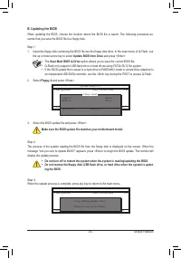
Page 62 - Unique Features; result in system malfunction.; -2 BIOS Update Utilities; design, which enhances protection for the; What is DualBIOS; update the backup BIOS manually.
Unique Features - 62 - 4-2-1 Updating the BIOS with the Q-Flash Utility A. Before You Begin 1. From GIGABYTE's website, download the latest compressed BIOS update file that matches your moth - erboard model. 2. Extract the file and save the new BIOS file (e.g. 770TD3L.f1) to your floppy disk, USB fl...
Page 63 - Update BIOS from Drive; Make sure the BIOS update file matches your motherboard model.; The; Save Main BIOS to Drive; option allows you to save the current BIOS file.
- 63 - Unique Features B. Updating the BIOS When updating the BIOS, choose the location where the BIOS file is saved. The following procedure as - sumes that you save the BIOS file to a floppy disk. Step 1: 1. Insert the floppy disk containing the BIOS file into the floppy disk drive. In the main me...
Page 64 - Load Optimized Defaults; dure is complete after the system restarts.
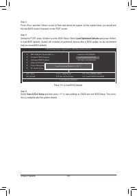
Unique Features - 64 - Step 4:Press <Esc> and then <Enter> to exit Q-Flash and reboot the system. As the system boots, you should see the new BIOS version is present on the POST screen. Step 5:During the POST, press <Delete> to enter BIOS Setup. Select Load Optimized Defaults and p...
Page 65 - C. After Updating the BIOS
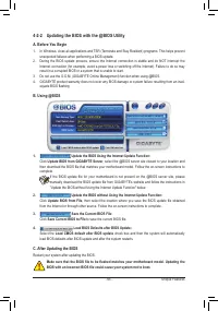
- 65 - Unique Features 4-2-2 Updating the BIOS with the @BIOS Utility A. Before You Begin 1. In Windows, close all applications and TSR (Terminate and Stay Resident) programs. This helps prevent unexpected failures when performing a BIOS update. 2. During the BIOS update process, ensure the Internet...
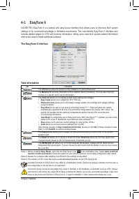
Page 66 - Tabs Information; Tab; without the need to install additional software.; The EasyTune 6 Interface
Unique Features - 66 - Available functions in EasyTune 6 may differ by motherboard model. Grayed-out area(s) indicates that the item is not configurable or the function is not supported. Incorrectly doing overclock/overvoltage may result in damage to the hardware components such as CPU, chipset, and...
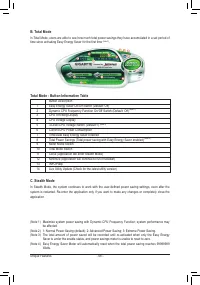
Page 67 - -4 Easy Energy Saver; Meter Mode - Button Information Table
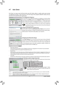
- 67 - Unique Features 4-4 Easy Energy Saver GIGABYTE Easy Energy Saver is a revolutionary technology that delivers unparalleled power savings with a click of the button. Featuring an advanced proprietary software design, GIGABYTE Easy Energy Saver is able to provide exceptional power savings and en...
Page 68 - Total Mode - Button Information Table
Unique Features - 68 - C. Stealth Mode In Stealth Mode, the system continues t o work with the user-defined power saving settings, even after the system is restarted. Re-enter the application only if you want to make any changes or completely close the application. (Note 1) Maximize system power sav...
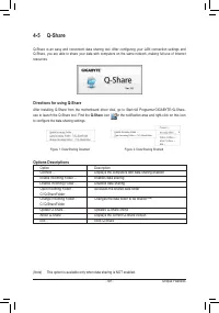
Page 69 - l. After configuring your LAN connection settings and; Directions for using Q-Share; in the notification area and right-click on this icon; Options Descriptions
- 69 - Unique Features 4-5 Q-Share Q-Share is an easy and convenient data sharing too l. After configuring your LAN connection settings and Q-Share, you are able to share your data with computers on the same network, making full use of Internet resources. Directions for using Q-Share After installin...
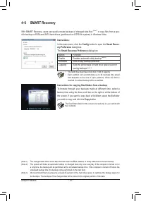
Page 70 - or copy files from a spe; Instructions for copying files/folders from a backup:; Config
Unique Features - 70 - 4-6 SMART Recovery With SMART Recovery, users can quickly create backups of changed data files (Note 1) or copy files from a spe - cific backup on PATA and SATA hard drives (partitioned on NTFS file system) in Windows Vista. Instructions for copying files/folders from a backup...
Page 71 - Selecting a system energy saving mode:; Configure; Con
- 71 - Unique Features 4-7 Auto Green Auto Green is an easy-to-use tool that provides users with simple options to enable system power savings via a Bluetooth cell phone. When the phone is out of the range of the computer's Bluetooth receiver, the sys- tem will enter the specified power saving mode....
Page 73 - Appendix; Chapter 5 Appendix; and operating system.; Before you begin; An empty formatted floppy disk.
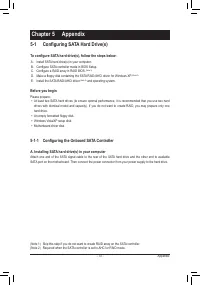
- 73 - Appendix Chapter 5 Appendix 5-1 Configuring SATA Hard Drive(s) To configure SATA hard drive(s), follow the steps below: A. Install SATA hard drive(s) in your computer. B. Configure SATA controller mode in BIOS Setup. C. Configure a RAID array in RAID BIOS. (Note 1) D. Make a floppy disk conta...
Page 74 - B. Configuring SATA controller mode in BIOS Setup
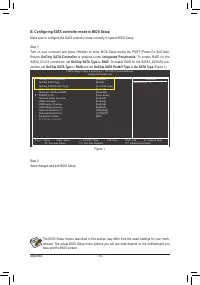
Appendix - 74 - B. Configuring SATA controller mode in BIOS Setup Make sure to configure the SATA controller mode correctly in system BIOS Setup. Step 1: Turn on your computer and press <Delete> to enter BIOS Setup during the POST (Power-On Self-Test). Ensure OnChip SATA Controller is enabled ...
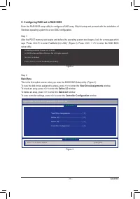
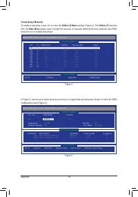
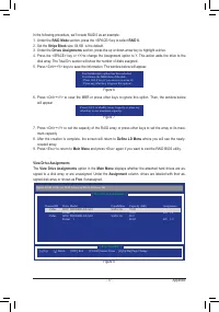
Page 75 - C. Configuring RAID set in RAID BIOS; Main Menu; To view the disk drives assigned to arrays, press <1> to enter the; View Drive Assignments; Figure 3
- 75 - Appendix C. Configuring RAID set in RAID BIOS Enter the RAID BIOS setup utility to configure a RAID array. Skip this step and proceed with the installation of Windows operating system for a non-RAID configuration. Step 1: After the POST memory test begins and before the operating system boot ...
Page 77 - Define LD Menu
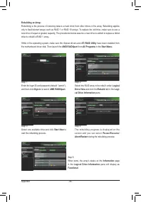
- 77 - Appendix In the following procedure, we'll create RAID 0 as an example.1. Under the RAID Mode section, press the <SPACE> key to select RAID 0 . 2. Set the Stripe Block size. 64 KB is the default. 3. Under the Drives Assignments section, press the up or down arrow key to highlight a driv...
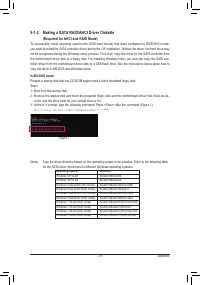
Page 79 - Operating System
- 79 - Appendix 5-1-2 Making a SATA RAID/AHCI Driver Diskette (Required for AHCI and RAID Mode) To successfully install operating system onto SATA hard drive(s) that is/are configured to RAID/AHCI mode, you need to install the SATA controller driver during the OS installation. Without the driver, th...
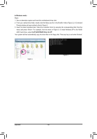
Page 81 - -1-3 Installing the SATA RAID/AHCI Driver and Operating System; A. Installing Windows XP; AMD AHCI Compatible RAID Controller-x86 platform
- 81 - Appendix 5-1-3 Installing the SATA RAID/AHCI Driver and Operating System With the SATA RAID/AHCI driver diskette and correct BIOS settings, you are ready to install Windows Vista/XP onto your hard drive(s). The followings are examples of Windows XP and Vista installation. A. Installing Window...
Page 82 - B. Installing Windows Vista; Load; folder and save the whole; SBxxxV; folder to; LH
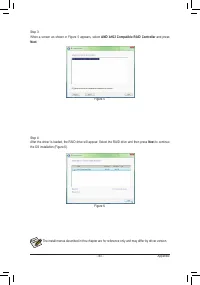
Appendix - 82 - B. Installing Windows Vista (The procedure below assumes that only one RAID array exists in your system.) Step 1: Restart your system to boot from the Windows Vista setup disk and perform standard OS installation steps. When a screen similar to that below appears (RAID hard drive wil...
Page 83 - AMD AHCI Compatible RAID Controller; and press; Next; to continue
- 83 - Appendix Step 3: When a screen as shown in Figure 5 appears, select AMD AHCI Compatible RAID Controller and press Next . Step 4: After the driver is loaded, the RAID drive will appear. Select the RAID drive and then press Next to continue the OS installation (Figure 6). Figure 5 Figure 6 The ...
Page 85 - A. Configuring Speakers; jack for microphone functionality.; icon; HD Audio Manager
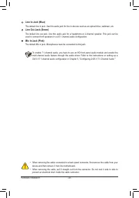
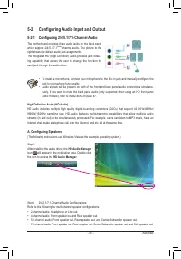
- 85 - Appendix 5-2-1 Configuring 2/4/5.1/7.1-Channel Audio The motherboard provides three audio jacks on the back panel which support 2/4/5.1/7.1 (Note) -channel audio. The picture to the right shows the default audio jack assignments. The integrated HD (High Definition) audio provides jack retask ...
Page 86 - Speaker Configura; according to; B. Configuring Sound Effect; You may configure an audio environment on the
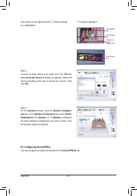
Appendix - 86 - The pictures to the right show the 7.1-channel speak- er configurations. Step 2:Connect an audio device to an audio jack. The The cur- rent connected device is dialog box appears. Select the device according to the type of device you connect. Then click OK . Step 3:On the Speakers sc...
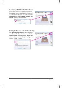
Page 87 - C. Activating an AC'97 Front Panel Audio Module
- 87 - Appendix If your chassis provides an AC'97 front panel audio mod-ule, to activate the AC'97 functionality, click the tool icon on the Speaker Configuration tab. On the Connector Settings dialog box, select the Disable front panel jack detection check box. Click OK to complete. Click Device ad...
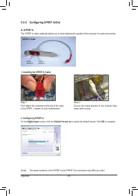
Page 88 - Digital Input; tab to select the default format. Click; OK
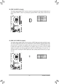
Appendix - 88 - 5-2-2 Configuring S/PDIF In/Out A. S/PDIF In The S/PDIF In cable (optional) allows you to input digital audio signals to the computer for audio processing. 1. Installing the S/PDIF In Cable: 2. Configuring S/PDIF In: On the Digital Input screen, click the Default Format tab to select...
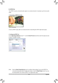
Page 89 - screen to configure further settings if you use the S/PDIF Out; Digital Output
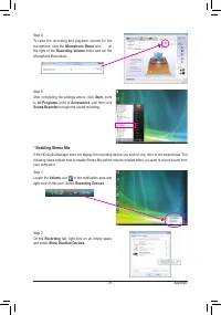
- 89 - Appendix B. S/PDIF Out The S/PDIF Out jacks can transmit audio signals to an external decoder for decoding to get the best audio quality. 1. Connecting a S/PDIF Out Cable: S/PDIF Coaxial Cable Connect a S/PDIF coaxial cable to an external decoder for transmitting the S/PDIF digital audio sign...
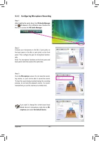
Page 90 - panel. Then configure the jack for microphone function; Microphone; and select; Set Default Device
Appendix - 90 - 5-2-3 Configuring Microphone Recording Step 1:After installing the audio driver, the HD Audio Manager icon will appear in the notification area. Double-click the icon to access the HD Audio Manager . Step 2:Connect your microphone to the Mic in jack (pink) on the back panel or the Mi...
Page 91 - in the notification area and; * Enabling Stereo Mix
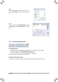
- 91 - Appendix Step 5:After completing the settings above, click Start , point to All Programs , point to Accessories , and then click Sound Recorder to begin the sound recording. Step 1:Locate the Volume icon in the notification area and right-click on this icon. Select Recording Devices . Step 2:...
Page 92 - Be sure to save the recorded audio file upon completion.; B. Playing the Recorded Sound; to config
Appendix - 92 - Step 3:When the Stereo Mix item appears, right-click on this item and select Enable . Then set it as the default de- vice. 5-2-4 Using the Sound Recorder A. Recording Sound 1. Make sure you have connected the sound input device (e.g. microphone) to the computer. 2. To record the audi...
Page 93 - Audio Device on High Definition Audio Bus
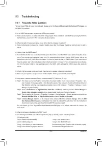
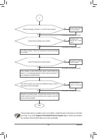
- 93 - Appendix 5-3 Troubleshooting 5-3-1 Frequently Asked Questions To read more FAQs for your motherboard, please go to the Support&Downloads\Motherboard\FAQ page on GIGABYTE's website. Q: In the BIOS Setup program, why are some BIOS options missing?A: Some advanced options are hidden in the B...
Page 99 - Contact Us
- 99 - Appendix Contact Us • GIGA-BYTE TECHNOLOGY CO., LTD. Address: No.6, Bao Chiang Road, Hsin-Tien Dist.,New Taipei City 231,Taiwan TEL: +886-2-8912-4000 FAX: +886-2-8912-4003Tech. and Non-Tech. Support (Sales/Marketing) :http://ggts.gigabyte.com.twWEB address (English): http://www.gigabyte.comWE...
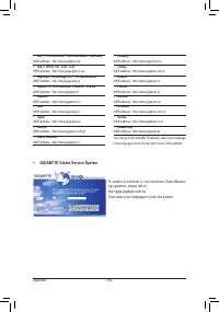
Page 100 - GIGABYTE Global Service System
Appendix - 100 - • G.B.T. TECHNOLOGY TRADING GMBH - Germany WEB address : http://www.gigabyte.de • G.B.T. TECH. CO., LTD. - U.K. WEB address : http://www.giga-byte.co.uk • Giga-Byte Technology B.V. - The Netherlands WEB address : http://www.giga-byte.nl • GIGABYTE TECHNOLOGY FRANCE - France WEB addr...


 Gigabyte B650
User Manual
Gigabyte B650
User Manual
 Gigabyte GA 770T D3L rev 1 x
User Manual
Gigabyte GA 770T D3L rev 1 x
User Manual
 Gigabyte GA 870A UD3 rev 2 2
User Manual
Gigabyte GA 870A UD3 rev 2 2
User Manual
 Gigabyte GA 880GA UD3H rev 2 2
User Manual
Gigabyte GA 880GA UD3H rev 2 2
User Manual
 Gigabyte GA 8I848P rev 1 x
User Manual
Gigabyte GA 8I848P rev 1 x
User Manual
 Gigabyte GA 8I848P rev 2 x
User Manual
Gigabyte GA 8I848P rev 2 x
User Manual
 Gigabyte GA 8IG1000 rev 1 x
User Manual
Gigabyte GA 8IG1000 rev 1 x
User Manual
 Gigabyte GA 8IG1000 rev 3 x
User Manual
Gigabyte GA 8IG1000 rev 3 x
User Manual
 Gigabyte GA 8IG1000 Pro rev 2 x
User Manual
Gigabyte GA 8IG1000 Pro rev 2 x
User Manual
 Gigabyte GA 8IPE1000 rev 1 x
User Manual
Gigabyte GA 8IPE1000 rev 1 x
User Manual
 Gigabyte GA 8IPE1000 rev 3 x
User Manual
Gigabyte GA 8IPE1000 rev 3 x
User Manual
 Gigabyte GA EX58 DS4 rev 1 0
User Manual
Gigabyte GA EX58 DS4 rev 1 0
User Manual
 Gigabyte GA EX58 UD3R rev 1 6
User Manual
Gigabyte GA EX58 UD3R rev 1 6
User Manual
 Gigabyte GA EX58 UD3R rev 1 7
User Manual
Gigabyte GA EX58 UD3R rev 1 7
User Manual
 Gigabyte GA EX58 UD3R SLI rev 1 0
User Manual
Gigabyte GA EX58 UD3R SLI rev 1 0
User Manual
 Gigabyte GA EX58 UD4 rev 1 0
User Manual
Gigabyte GA EX58 UD4 rev 1 0
User Manual
 Gigabyte GA EX58 UD5P rev 1 0
User Manual
Gigabyte GA EX58 UD5P rev 1 0
User Manual
 Gigabyte GA GC330UD rev 1 0
User Manual
Gigabyte GA GC330UD rev 1 0
User Manual
 Gigabyte GA H55 UD3H rev 1 0
User Manual
Gigabyte GA H55 UD3H rev 1 0
User Manual
 Gigabyte GA H55 UD3H rev 1 3
User Manual
Gigabyte GA H55 UD3H rev 1 3
User Manual