Page 2 - Before You Use Your Microwave; CONTENTS; General information; Attach Mounting Plate to Wall; Installation Instructions
Before You Use Your Microwave CONTENTS General information Important Safety Instructions .................................. 3 Electrical Requirements .......................................... 3 Damage – Shipment/Installation.............................. 4 Parts Included...............................
Page 4 - If the unit is damaged in shipment,; return the; If the unit is damaged by the customer,; repair or; If the unit is damaged by the installer; Some extra parts are included.; HARDWARE PACKET; PART; PARTS INCLUDED; ADDITIONAL PARTS; Manual
PART QUANTITY Wood Screws 2 ( 1 ⁄ 4 “ x 2“) Toggle Bolts (andwing nuts) ( 3 ⁄ 16 “ x 3“) Self-Aligning Machine 3 Screws ( 1 ⁄ 4 “-28 x 3 1 ⁄ 4 “) Nylon Grommet(for metal cabinets) 1 • If the unit is damaged in shipment, return the unit to the store in which it was bought for repairor replacement. • ...
Page 5 - TOOLS YOU WILL NEED; or; MOUNTING SPACE; The space between the cabinets must be; out from wall using adequate materials supporting
TOOLS YOU WILL NEED # 1 Phillips screwdriver Pencil Ruler or tape measure andstraight edge Carpenter square(optional) Tin snips (for cuttingdamper, if required) Electric drill with 3 ⁄ 16 “ , 1 ⁄ 2 “ and 5 ⁄ 8 “ drill bits Hammer (optional) Stud finder or Filler blocks or scrapwood pieces, if needed...
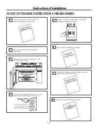
Page 6 - Draw a line down the center of the studs.; FINDING THE WALL STUDS; Pull the carton up and off the oven.; Cut the middle of the outer protective plastic bag to; Remove the installation instructions,use and care,
PLACEMENT OF THE MOUNTING PLATE 1 Installation Instructions Find the studs, using one of the followingmethods: A. Stud finder – a magnetic device whichlocates nails. B. Use a hammer to tap lightly across themounting surface to find a solid sound.This will indicate a stud location. After locating the...
Page 7 - DETERMINING WALL PLATE LOCATION UNDER YOUR CABINET; THE MICROWAVE MUST BE LEVEL.
DETERMINING WALL PLATE LOCATION UNDER YOUR CABINET C. Installation Instructions Plate position flat bottom cabinet Draw a line on the back wall equal to the depth of the front overhang. to Cooktop C 3/8" TO EDGE ...
Page 8 - ALIGNING THE WALL PLATE; Wear gloves; Draw a vertical line on the wall at the center of the; NOTE: DO NOT MOUNT THE PLATE AT THIS; Holes A and B are inside area E. If neither of; at least one wood screw; m ounted; firmly in a stud; to support the weight of the; Set the mounting plate aside
Installation Instructions ALIGNING THE WALL PLATE D. CAUTION: Wear gloves to avoid cutting fingers onsharp edges. Area E Hole A Hole B Centerlinenotches Draw a Vertical Line on Wall from Center of Top Cabinet Draw a horizontal line on wall at thebottom of “Rear Wall Template”. Horizontal Line Horizo...
Page 9 - INSTALLATION TYPES; OUTSIDE TOP EXHAUST; Adaptor in Place for
A INSTALLATION TYPES This microwave oven is designed for adaptation tothe following three types of ventilation: A. Outside Top Exhaust (Vertical Duct)B. Outside Back Exhaust (Horizontal Duct)C. Recirculating (Non-Vented Ductless) proceed to that section. OUTSIDE TOP EXHAUST (VERTICAL DUCT) OUTSIDE B...
Page 10 - Total Ductwork; Maximum duct length:; INSTALLATION INSTRUCTIONS FOR EXTERNAL EXHAUST DUCTING; diameter duct is acceptable to use.
EQUIVALENT NUMBER EQUIVALENT DUCT PIECES LENGTH x USED = LENGTH Rectangular-to-Round 5 Ft. (1.5 m) x ( ) = Ft. or m Transition Adaptor* Wall Cap 40 Ft. (12.2 m) x ( ) = Ft. or m 90° Elbow 10 Ft. (3 m) x ( ) = Ft. or m 45° Elbow 5 Ft. (1.5 m) x ( ) = Ft. or m 90° Elbow 25 Ft. (7.6 m) x ( ) = Ft. or m...
Page 11 - Roof Cap; Wall Cap; Total Length; EXTERNAL EXHAUST DUCTING
EQUIVALENT NUMBER EQUIVALENT DUCT PIECES LENGTH x USED = LENGTH Roof Cap 24 Ft. (7.3 m) x (1) = 24 Ft. (7.3 m) 12 Ft. (3.6 m) Straight Duct 12 Ft. (3.6 m) x (1) = 12 Ft. (3.6 m) (6”/15.2 cm Round) Rectangular-to-Round 5 Ft. (1.5 m) x (1) = 5 Ft. (1.5 m) Transition Adaptor* Equivalent lengths of duct...
Page 12 - INSTALLATION OVERVIEW; Wall
Place the mounting plate against the wall andinsert the toggle wings into the holes in the wall to mount the plate. NOTE: Before tightening toggle bolts and wood screw, make sure the bottom of the mounting platetouch the bottom of the cabinet when pushed flush against the wall and that the plate is ...
Page 13 - EXHAUST; Place the blower unit back into the opening.; Openings Facing Top; with the top of the unit facing up.
USE TOP CABINET TEMPLATEFOR PREPARATION OF TOPCABINET You need to drill holes for the top support screws, ahole large enough for the power cord to fit through,and a cutout large enough for the exhaust adaptor. A2. • Read the instructions on the TOP CABINET TEMPLATE. • Tape it underneath the top cabi...
Page 14 - IMPORTANT: If filler blocks are; Exhaust Adaptor; heat shield and door.
3 MOUNT THE MICROWAVEOVEN FOR EASIER INSTALLATION AND PERSONALSAFETY, WE RECOMMEND THAT TWO PEOPLEINSTALL THIS MICROWAVE OVEN. NOTE: If your cabinet is metal, use the nylon grommet around the power cord hole to prevent cutting of the cord. NOTE: We recommend using filler blocks if the cabinet front ...
Page 15 - Attach the microwave oven to the top cabinet.; CONNECTING DUCTWORK; furnance; for high temperature applications.
4 Attach the microwave oven to the top cabinet. 7 Cabinet Front Cabinet Bottom Shelf Tighten the outer two screws to the top of themicrowave oven. (While tightening screws, holdthe microwave oven in place against the wall andthe top cabinet.) Filler Block Microwave Oven Top Equivalent to Depth of Ca...
Page 16 - Blower Plate; REMOVE BLOWER PLATE
INSTALLATION OVERVIEW B1. Prepare Rear Wall B3. Attach Mounting Plate to Wall B4. Prepare Top Cabinet B5. Adjust Blower B6. Mount the Microwave Oven IMPORTANT NOTES: • Make sure the screws for the blower motor and blower plate are securely tightened when they are reinstalled. This will help to preve...
Page 17 - USE TOP CABINET TEMPLATE; Roll the blower unit 90°
ATTACH THE MOUNTINGPLATE TO THE WALL B3. • Read the instructions on the TOP CABINETTEMPLATE. • Tape it underneath the top cabinet. • Drill the holes, following the instructions on theTOP CABINET TEMPLATE. CAUTION: Wear safety goggles when drilling holes in the cabinet bottom. Wall Mounting Plate Spa...
Page 18 - Remove the knockout plates in the back of the unit
Attach the exhaust adaptor to the rear of theoven by sliding it into the guides at the topcenter of the back of the oven. AFTER: Fan BladeOpenings Facing Back Place the blower unit back into the opening. Replace the blower plate in the same positionas before with the screw. Make sure the screw is ti...
Page 19 - IMPORTANT: If filler blocks are not; Cabinet Front; IMPORTANT: Do not grip or use the handle
Attach the microwave oven to the top cabinet. Installation Instructions 3 MOUNT THE MICROWAVEOVEN B6. FOR EASIER INSTALLATION AND PERSONALSAFETY, WE RECOMMEND THAT TWO PEOPLEINSTALL THIS MICROWAVE OVEN. NOTE: If your cabinet is metal, use the nylon grommet around the power cord hole to preventcuttin...
Page 20 - RECIRCULATING
INSTALLATION OVERVIEW C1. Attach Mounting Plate to Wall C2. Prepare Top Cabinet C4.C5. Mount the Microwave Oven IMPORTANT NOTES: • Make sure the screws for the blower motor and blowerplate are securely tightened when they are reinstalled.This will help to prevent excessive vibration. • Make sure the...
Page 21 - MOUNT THE MICROWAVE OVEN
Installation Instructions Attach the microwave oven to the top cabinet. Cabinet Front Cabinet Bottom Shelf Filler Block Microwave Oven Top Equivalent to Depthof Cabinet Recess 3 MOUNT THE MICROWAVE OVEN FOR EASIER INSTALLATION AND PERSONALSAFETY, WE RECOMMEND THAT TWO PEOPLEINSTALL THIS MICROWAVE OV...
Page 22 - MOUNT THE MICROWAVE; packed with the microwave.; C5. INSTALLING OR CHANGE; Unplug microwave oven or disconnect power.
Installation Instructions 5 MOUNT THE MICROWAVE OVEN (cont.) 8 7 Tighten the outer two screws to the top of themicrowave oven. (While tightening screws, holdthe microwave oven in place against the wall andthe top cabinet.) Insert 2 self-aligning screwsthrough outer top cabinetholes. Turn two full tu...
Page 23 - Close the microwave door. Plug in microwave
Installation Instructions Close the microwave door. Plug in microwave oven or reconnect power. Reinstall the vent by sliding the bottom of the vent into place. Push the vent top into position and slide right into place. Replace the two vent mounting screws located on top of the microwave using a #1 ...
Page 24 - BEFORE YOU USE YOUR MICROWAVE; INST; ring a nd glas s tray in; DDDDDDD; PRODU; Read the; REGIS; U SE; Replace house fuse or turn breaker back on.; FILL OUT PRODUCT R EGISTRATION CAR D
Remove all packing material from the microwave oven. 2. Make sure the microwave oven has beeninstalled according to instructions. 1. BEFORE YOU USE YOUR MICROWAVE Ensure properground existsbefore use INST ALLA TION INSTR UCTIONS 3. D G DDDDDDD Installation Instructions ring a nd glas s tray in cavit...
Page 25 - Printed in China
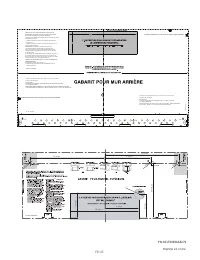
Printed in China 3/8" TO EDGE NOTE: IT IS VE RY IMPORTANT TO READ AND FOLLO W THE DIRECTIO N...
Page 26 - Lea estas instrucciones completamente y con atención.; Nota para el consumidor:; • Nivel de preparation tecnica:; La instalacion correcta es responsabilidad del instalador.
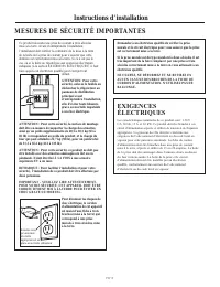
LEA CUIDADOSAMENTE. CONSERVE ESTAS INSTRUCCIONES. . Lea estas instrucciones completamente y con atención. • • • • Nota para el consumidor: • Nivel de preparation tecnica: • La instalacion correcta es responsabilidad del instalador. • Las fallas del producto que resulten de una instalación incorrecta...
Page 27 - Antes de usar el horno microondas; CONTENIDO; Información general; Instrucciones de instalación; La información de plantilla
Antes de usar el horno microondas CONTENIDO Información general Guía de la instalación paso a paso Extracción superior externa Montaje de instalación la placa de en la ......................................................................12 Preparación del gabinete superior .....................13 V...
Page 29 - Tornillos para madera; PIEZA; KIT DE FERRETERÍA; PIEZA; Si el producto ha resultado dañado durante su envío
Tornillos para madera ( " x 2") Tornillos de fiador (y tuercas de mariposa) ( " x 3") Tornillos autoalinea-ntes para máquina ( "-28 x3 ") Moldura aislante de nylon (para los gabinetes metálicos) • • • DAÑOS-ENVÍO (TRANSP-ORTE)/INSTALACIÓN Instrucciones de instalación PIEZAS I...
Page 30 - Cinta aislante y cinta de pintor
HERRAMIENTAS NECESARIAS Destornillador Phillips #1 Lápiz Regla o cinta métrica con borde recto Escuadra de carpintero (opcional) Martillo (opcional) Detector de vigas(entramado) o Guantes Nivel Instrucciones de instalación Gafas de seguridad ESPACIO PARA LA INSTALACIÓN • • • Protector contra salpica...
Page 31 - Tornillos; Adaptador de escape; Bolsa de accesorios pequeña; Bandeja de vidrio
COLOCACIÓN DE LA PLACA DE INSTALACIÓN 1 Instrucciones de instalación 1 LOCALIZACIÓN DE LAS VIGAS DE LA PARED B. A. 2 Vigas de la pared Centro 3 Caja de cartón Tire de la caja de cartón hacia arriba, para separarla del horno. 2 Espuma de poliestireno 3 1 Tornillos Tornillos Placa de instalación 5 4 C...
Page 32 - UBICACIÓN DE LA PLACA PARA LA PARED DE BAJO DEL GABINETE; EL MICROONDAS DEBE QUEDAR NIVELADO.
C . C 3/8" TO EDGE NOTE: IT IS V ERY IMPOR TANT TO READ AND F OLLOW THE DIRECTION S IN THE...
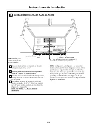
Page 33 - ALINEACIÓN DE LA PLACA PARA LA PARED; Los Agujero A y los Agujero B se encuentran; que al menos un tornillo para madera; quede fijado; firmemente a una viga; pueda soportar el peso del microondas.; Deje a un lado
Instrucciones de instalación D. CL 3/8" TO EDGE NOTE: IT IS VERY IMPORTANT TO READ AND FOLLOW THE DIRECTIONS IN THE INSTALLATION INSTRUCTIONS BEFORE PROCEEDING WITH THIS REAR WALL TEMPLATE. This Rear Wall Template serves to position the bottom mounting plate and to locate the horizontal exhaust ...
Page 34 - TIPOS DE INSTALACIÓN; este horno microondas se ha fábricado para un; Consulte la página 12
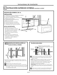
A TIPOS DE INSTALACIÓN (A Elección Entre A, B o C) Este horno microondas está diseñado para adaptarse a los tres tipos siguientes de ventilación:A. Extracción superior externa (conducto vertical)B. Extracción trasera externa (conducto horizontal)C. Recirculación (sin conducto de extracción) EXTRACCI...
Page 35 - PIEZAS DEL CONDUCTO; Tapa de salida a la pared; INSTRUCCIONES DE INSTALACIÓN DE CONDUCTOS DE ESCAPE EXTERNAS; en caso de que sea necesario instalar conductos, tenga en cuenta; Asimismo, asegúrese de que los reguladores de; representan áreas de resistencia adicional al flujo del; Largo total del sistema de conductos =; Conexión de escape; redondo, se debe utilizar un adaptador de transición.
= x PIEZAS DEL CONDUCTO Adaptador de unión entre el conducto rectangular y el redondo* Pies o m (metros) = ) ( x 5 pies (1,5 m) Tapa de salida a la pared = ) ( x 10 pies (3 m) ° Codo de 90 = ) ( x 5 pies (1,5m) ° Codo de 45 = ) ( x 25 pies (7,6 m) ° Codo de 90 = ) ( x 5 pies (1,5 m) ° Codo de 45 = )...
Page 36 - EXTRACCIÓN SUPERIOR EXTERNA (SÓLO EJEMPLO); EXTRACCIÓN TRASERA EXTERNA (SÓLO EJEMPLO); CONDUCTOS DE ESCAPE EXTERNAS; Tapa d salida al techo
La siguiente tabla contiene un ejemplo de una posible instalación de un sistema de conducto de extracción. EXTRACCIÓN SUPERIOR EXTERNA (SÓLO EJEMPLO) La siguiente tabla contiene un ejemplo de uno posible instalación de un sistema de conducto de extracción. Instrucciones de instalación EXTRACCIÓN TRA...
Page 37 - Para utilizar tornillos de fiador:; EXTRACCIÓN SUPERIOR EXTERNA; antes de apretar los tornillos de fiador y el tornillo para
3 4 MONTAJE DE INSTALACIÓN LA PLACA DE EN LA PARED A1. 1 Pared Placa de instalación El espacio que ocupan los tornillos fiadores es superior al grueso de la pared Extremo de tornillo Tornillo fiador Tuercas de mariposa Para utilizar tornillos de fiador: Instrucciones de instalación 2 EXTRACCIÓN SUPE...
Page 38 - Antes de girar; Vuelva a colocar el ventilador dentro de su abertura.; No tire hacia afuera ni estire los cables
A2. • • • Instrucciones de instalación A3. Placa del ventilador Tornillo del motor del ventilador Parte trasera del microondas 2 Extremo B Extremo A 1 3 Parte trasera del microondas Antes de girar Después de girar Parte trasera del microondas Parte trasera del microondas Parte trasera del microondas...
Page 39 - DOS PERSONAS
3 2 1 Adaptador de extracción Placa del ventilador Regulador de extracción Parte trasera del microondas • • A3. 5 Parte trasera del microondas 6 7 Parte trasera del microondas Adaptador Guía Lengüetas de Bloqueo A4 . A5 . Instrucciones de instalación Fije el ventilador al microondas con el tornillo ...
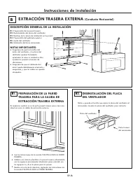
Page 41 - EXTRACCIÓN TRASERA EXTERNA; DESCRIPCIÓN GENERAL DE LA INSTALACIÓN
• • Parte trasera del microondas Instrucciones de instalación B1. •• • B2. B Placa del ventilador 3/8" TO EDGE ...
Page 42 - B4. USO DE LA PLANTILLA PARA EL
Instrucciones de instalación SP-17 B3. • • • Pared Placa de instalación El espacio que ocupan los tornillos fiadores es superior al grueso de la pared Tornillo fiador Tuercas de mariposa Para utilizar tornillos de fiador: Extremo de tornillo 12 3 4 2 1 B5. Extremo B Extremo A Parte trasera del micro...
Page 43 - Retire las placas preperforadas en la parte trasera
Instrucciones de instalación B5. 3. o Parte trasera del microondas4. o. Parte trasera del microondasParte trasera del microondas5. 6. Parte trasera del microondas SP-18 Vuelva a colocar el ventilador dentro de su abertura. B5. Gire el ventilador hacia la izquierda 180°. Antes del giro Después del gi...
Page 45 - RECIRCULACIÓN; Pared
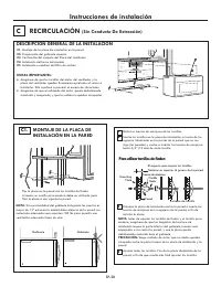
• • Instrucciones de instalación C1. 1 2 C Gabinete Gabinete NOTAS IMPORTANTES: RECIRCULACIÓN (Sin Conducto De Extracción) DESCRIPCIÓN GENERAL DE LA INSTALACIÓN C1. Montaje de la placa de instalación en la pared C2. Preparación del gabinete superior C3. Verificación del conjunto del Placa del Ventil...
Page 46 - Placa del Ventilador; No agarre ni use la manija o el escudo térmico
Instrucciones de instalación C3. C4. Placa del Ventilador • • C2. • • • Lea las instrucciones de la sección PLANTILLA PARA EL GABINETE SUPERIOR.Adhiera con cinta la plantilla al gabinete superior. USO DE LA PLANTILLA PARA EL GABINETE SUPERIOR A FIN DE PREPARAR EL ÁREA DE DICHO GABINETE Es necesario ...
Page 47 - El filtro de carbón está instalado de fábrica en algunos
5 8 7 C4. Instale los filtros de grasa. Consulte el Manual del usuario provisto con el microondas. Instrucciones de instalación INSTALACIÓN DEL HORNO MICROONDAS (cont.) Inserte 2 tornillos autoalineantes a través de los agujeros exteriores del gabinete superior. Apriete cada uno de, los tornillos do...
Page 48 - Presione la parte inferior del filtro de carbón para colocarlo
Instrucciones de instalación Reinstale el ducto deslizando la parte inferior del mismo hacia su lugar. Empuje la parte superior en su posición y deslicela hacia la derecha. Remplace los dos tornillos ubicados en la parte superior utilizando un destornillador Phillips #1. 5 6 7 Presione la parte infe...
Page 49 - ANTES DE USAR EL HORNO MICROONDAS; LIENE LA TARJETA DE REGISTRO DEL PRODUCTO.
2. 1. ANTES DE USAR EL HORNO MICROONDAS INSTRUCCIONES DE INSTALACIÓN 3. Instrucciones de instalación 4. 7. 6. INSTRUCCIONES DE INSTALACIÓN GUÍA DE USO Y CUID ADO REGISTR O DEL PRODUCT O Lea el manual de use y cuidado. Vuelva a colocar el fusible correspondiente o encienda de nuevo el disyuntor. 5. ....
Page 50 - Impreso en China; PLANTILLA PARA EL GABINETE SUPERIOR
Impreso en China " 2 / 1 - 4 3/8" 3/8" 13-3/8" 8-1/4" 2" 12-1/2" 6-1/4" " 2 3 / 7 2 - 9 " 4 / 1 - 4 3/8" 13-3/8" 3/8" HASTA EL EXTREMO ANCHO MÍNIMO DE 30" REQUERIDO Corte la plantilla ubicada en la pared de atrás a través de la linea de puntos. Corte la plantilla...
Page 51 - Remarque destinée à l’installateur –; VEUILLEZ LIRE ATTENTIVEMENT.; AVANT DE COMMENCER; Des questions? Appelez au; ou
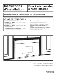
Instructionsd’installation Four à micro-ondes à hotte intégrée Lisez attentivement toutes ces instructions. • IMPORTANT – Conservez ces instructions pour l’inspecteur local. • IMPORTANT – Respectez tous les codes et règlements en vigueur. • Remarque destinée à l’installateur – Assurez- vous de laiss...
Page 52 - Instructions d’installation; Renseignements généraux
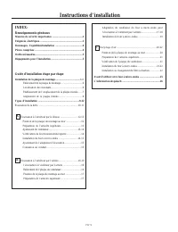
Instructions d’installation INDEX: Renseignements généraux Guide d’installation étape par étape B A C Évacuation à l’extérieur par le dessus ...........................12-15 Évacuation à l’extérieur par l’arrière ..............................16-19 Recyclage d’air ......................................
Page 54 - PIÈCES COMPRISES; SACHET DE QUINCAILLERIE
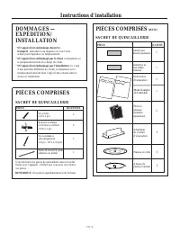
Instructions d’installation DOMMAGES — EXPÉDITION/ INSTALLATION • Si l’appareil est endommagé durant le transport , retournez-le au magasin où vous l’avez acheté pour réparation ou remplacement. • Si l’appareil est endommagé par le client , la réparation ou le remplacement reste à la charge du clien...
Page 55 - OUTILS NÉCESSAIRES; su p
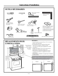
Instructions d’installation DÉGAGEMENTS POUR L’INSTALLATION Tournevis Phillips n o 1 Règle ou ruban à mesurer et règle droite Équerre de menuisier (facultative) Cisailles de ferblantier (pour couper le registre, si nécessaire) Ciseaux (pour couper le gabarit, si nécessaire) Perceuse électrique avec ...
Page 56 - LOCALISATION DES MONTANTS; LE FOUR À MICRO-ONDES DOIT ÊTRE FIXÉ À; ENLEVER LE FOUR À MICRO-ONDES
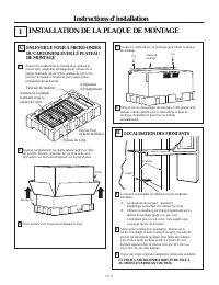
Instructions d’installation INSTALLATION DE LA PLAQUE DE MONTAGE 1 LOCALISATION DES MONTANTS B. Localisez les montants en utilisant une des méthodes suivantes : A. Localisateur de montant – dispositif magnétique permettant de localiser les clous. B. Utilisez un marteau pour frapper légèrement sur la...
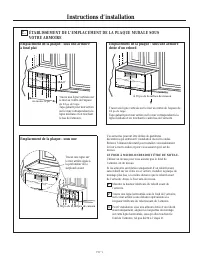
Page 57 - LE FOUR À MICRO-ONDES DOIT ÊTRE DE NIVEAU.; ÉTABLISSEMENT DE L’EMPLACEMENT DE LA PLAQUE MURALE SOUS; Emplacement de la plaque - sous une armoire; À 30 po de la surface de cuisson
Instructions d’installation Vos armoires peuvent être dotées de garnitures décoratives qui entravent l’installation du micro-ondes. Enlevez l’élément décoratif pour installer convenablement le four à micro-ondes et pour vous assurer qu’il est de niveau. LE FOUR À MICRO-ONDES DOIT ÊTRE DE NIVEAU. Uti...
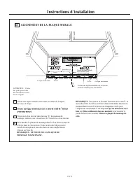
Page 58 - ALIGNEMENT DE LA PLAQUE MURALE; REMARQUE : NE FIXEZ PAS LA PLAQUE DE
Instructions d’installation 3 2 1 ATTENTION : Portezdes gants pour éviterde vous blesser sur lesbords coupants. ALIGNEMENT DE LA PLAQUE MURALE D. Tracez une ligne horizontale sur le mur de La ligne horizontale La ligne horizontale Trou A Trou B Zone E Encoches de la ligne centrale " " de 24 ...
Page 59 - Ce four à micro-ondes est conçu pour s’adapter aux trois types; ÉVACUATION À L’EXTÉRIEUR PAR; d’une; décidez de recycler l’air dans la pièce, rendez-vous à la page 20.; Consultez la page 12
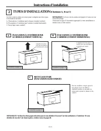
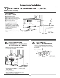
Instructions d’installation TYPES D’INSTALLATION (Choisissez A, B ou C) 2 Ce four à micro-ondes est conçu pour s’adapter aux trois types d’évacuation suivants : A. Évacuation à l’extérieur par le dessus (conduit vertical)B. Évacuation à l’extérieur par l’arrière (conduit horizontal)C. Recyclage (san...
Page 60 - Longueur maximale du conduit:; INSTRUCTIONS POUR L`INSTALLATION EXTERIEURE
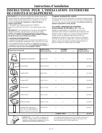
Instructions d’installation L’évacuation vers l’extérieur requiert un CONDUIT D’ÉVACUATION POUR HOTTE. Lisez attentivement ce qui suit. REMARQUE: Il est important que l’évacuation soit installée en utilisant le chemin le plus direct et avec le moins de coudes possible. Cela assure une bonne évacuati...
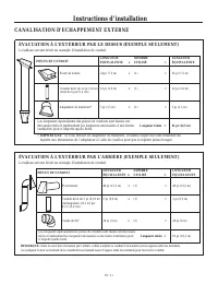
Page 61 - CANALISATION D'ECHAPPEMENT EXTERNE; ÉVACUATION À L’EXTÉRIEUR PAR LE DESSUS (EXEMPLE SEULEMENT); ventilation pour n’importe quelle hotte.; ÉVACUATION À L’EXTÉRIEUR PAR L’ARRIÈRE (EXEMPLE SEULEMENT); Le tableau suivant décrit un exemple d’installation de conduit.
Instructions d’installation CANALISATION D'ECHAPPEMENT EXTERNE ÉVACUATION À L’EXTÉRIEUR PAR LE DESSUS (EXEMPLE SEULEMENT) Le tableau suivant décrit un exemple d’installation de conduit. Évent de toiture Conduit droit de 12 pi (3,6 m) (rond de 6 po/15,2 cm) Adaptateur de transition* Les longueurs équ...
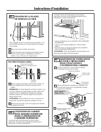
Page 62 - VUE D’ENSEMBLE; Pour utiliser les boulons à ailettes :; FIXATION DE LA PLAQUE; REMARQUES IMPORTANTES :
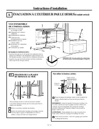
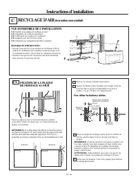
Instructions d’installation ÉVACUATION À L’EXTÉRIEUR PAR LE DESSUS (Conduit vertical) A VUE D’ENSEMBLE DE L’INSTALLATION A1. Fixation de la plaque de montage au mur A2. Préparation de l’armoire supérieure A3. Vérification du fonctionnement du registre A4. Installation du four à micro-ondes A5. Ajust...
Page 63 - orientées vers le haut.; ATTENTION : Ne tirez pas sur les fils de l’ensemble
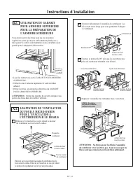
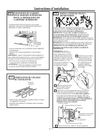
Instructions d’installation UTILISATION DU GABARIT POUR ARMOIRE SUPÉRIEURE POUR LA PRÉPARATION DE L’ARMOIRE SUPÉRIEURE A2. Vous devez percer des trous pour les vis de soutien supérieures, ainsi qu’un trou suffisamment grand pour y faire passer le cordon d’alimentation et une ouverture assez grande p...
Page 65 - INSTALLATION DU FOUR
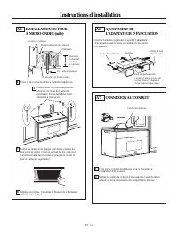
Instructions d’installation INSTALLATION DU FOUR À MICRO-ONDES (suite) Avant de l’armoire Étagère inférieure de l’armoire Entretoise Vis à auto-alignement Dessus du four à micro-ondes Équivalent à la hauteur du rebord de l’armoire Fixez le four à micro-ondes à l’armoire supérieure. 4 Serrez les deux...
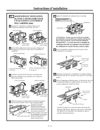
Page 68 - ADAPTATION DU VENTILATEUR; REMARQUE : Les ouvertures de l’ensemble du
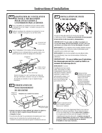
Instructions d’installation ADAPTATION DU VENTILATEUR DU FOUR À MICRO-ONDES POUR L’ÉVACUATION À L’EXTÉRIEUR PAR L’ARRIÈRE (suite) B5. Retournez l’ensemble du ventilateur dans le sens contraire des aiguilles d’une montre, sur 180°. Enlevez délicatement les fils des encoches. Replacez les fils dans le...
Page 69 - IMPORTANT: Si vous n’utilisez pas
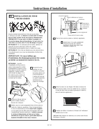
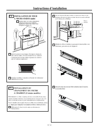
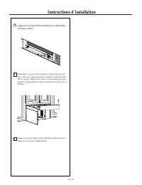
Instructions d’installation INSTALLATION DU FOUR À MICRO-ONDES B6. REMARQU: Lors de l’installation du four à micro- ondes, faites passer le cordon d’alimentation à travers le trou situé dans le fond de l’armoire supérieure. Gardez-le bien serré durant les étapes 1 à 3. Ne coincez pas le cordon ou ne...


 Frigidaire FFMV1846VB
User Manual
Frigidaire FFMV1846VB
User Manual
 Frigidaire FFMV1846VW
User Manual
Frigidaire FFMV1846VW
User Manual
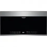 Frigidaire FGBM19WNVF
User Manual
Frigidaire FGBM19WNVF
User Manual
 Frigidaire FMBS2227AB
User Manual
Frigidaire FMBS2227AB
User Manual
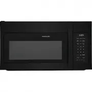 Frigidaire FMOS1846BB
User Manual
Frigidaire FMOS1846BB
User Manual
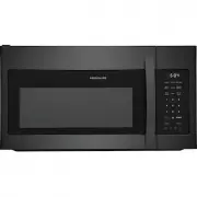 Frigidaire FMOS1846BD
User Manual
Frigidaire FMOS1846BD
User Manual
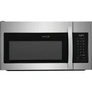 Frigidaire FMOS1846BS
User Manual
Frigidaire FMOS1846BS
User Manual
 Frigidaire FMOS1846BW
User Manual
Frigidaire FMOS1846BW
User Manual
 Frigidaire FMOW1852AS
User Manual
Frigidaire FMOW1852AS
User Manual
 Frigidaire GCWM2767AD
User Manual
Frigidaire GCWM2767AD
User Manual
 Frigidaire GMBD3068AF
User Manual
Frigidaire GMBD3068AF
User Manual