Page 3 - CONTENTS; General information; Installation Instructions; Attach Mounting Plate to Wall
CONTENTS General information Important Safety Instructions .................................. 3 Electrical Requirements .......................................... 3 Damage – Shipment/Installation.............................. 4 Parts Included.............................................................
Page 5 - If the unit is damaged in shipment,; return the; If the unit is damaged by the customer,; repair or; If the unit is damaged by the installer; Some extra parts are included.; HARDWARE PACKET; PART; PARTS INCLUDED; ADDITIONAL PARTS; Shelf; For some models
PART QUANTITY Wood Screws 2 ( 1 ⁄ 4 “ x 2“) Toggle Bolts (andwing nuts) ( 3 ⁄ 16 “ x 3“) Self-Aligning Machine 3 Screws ( 1 ⁄ 4 “-28 x 3 1 ⁄ 4 “) Nylon Grommet(for metal cabinets) 1 • If the unit is damaged in shipment, return the unit to the store in which it was bought for repairor replacement. • ...
Page 6 - bottom cabinets; Mounting Space; or more from the; Backsplash; Clearance
Installation Instructions • Tape measure• Hole saw• Stud finder or hammer• Level• Duct and masking tape• Scissors • #1 Phillips screw driver• Electric drill• 3/16”, 1/2”, 5/8” drill bit• Filler wood blocks for recessed bottom cabinets • Tin snips Mounting Space Tools you will need: • The space betwe...
Page 7 - Draw a line down the center of the studs.; FINDING THE WALL STUDS; Pull the carton up and off the oven.; Screws; Cut the middle of the outer protective plastic bag to; Filters and Turntable
PLACEMENT OF THE MOUNTING PLATE 1 Installation Instructions Find the studs, using one of the followingmethods: A. Stud finder – a magnetic device whichlocates nails. B. Use a hammer to tap lightly across themounting surface to find a solid sound.This will indicate a stud location. After locating the...
Page 8 - DETERMINING WALL PLATE LOCATION UNDER YOUR CABINET; THE MICROWAVE MUST BE LEVEL.
DETERMINING WALL PLATE LOCATION UNDER YOUR CABINET C. Installation Instructions Plate position flat bottom cabinet to Cooktop C 3/8" TO EDGE ...
Page 9 - ALIGNING THE WALL PLATE; NOTE: DO NOT MOUNT THE PLATE AT THIS; Holes A and B are inside area E. If neither of; at least one wood screw; m ounted; firmly in a stud; to support the weight of the; Set the mounting plate aside
Installation Instructions ALIGNING THE WALL PLATE D. Area E Hole A Hole B Centerlinenotches Draw a Vertical Line on Wall from Center of Top Cabinet Draw a horizontal line on wall at thebottom of “Rear Wall Template”. Horizontal Line Horizontal Line CL 3/8" TO EDGE %#76+10Ä+(':*#756#ਸ਼+52...
Page 10 - INSTALLATION TYPES; OUTSIDE TOP EXHAUST; Adaptor in Place for; RECIRCULATING; NOTE: Read the pages 14-15 only if you plan to vent your exhaust to the
INSTALLATION TYPES This microwave oven is designed for adaptation tothe following three types of ventilation: B. Outside Back Exhaust (Horizontal Duct) proceed to that section. OUTSIDE TOP EXHAUST (VERTICAL DUCT) OUTSIDE BACK EXHAUST (HORIZONTAL DUCT) See page 2 0 Adaptor in Place for Outside Top Ex...
Page 11 - INSTALLATION OVERVIEW; out from wall using adequate materials supporting
INSTALLATION OVERVIEW Attach Mounting Plate to WallPrepare Top Cabinet Mount the Microwave Oven IMPORTANT NOTES: • Make sure the screws for the blower motor and blowerplate are securely tightened when they are reinstalled.This will help to prevent excessive vibration. • Make sure the motor wiring ha...
Page 12 - MOUNT THE MICROWAVE OVEN; USE TOP CABINET TEMPLATE
Installation Instructions Attach the microwave oven to the top cabinet. Cabinet Front Cabinet Bottom Shelf Filler Block Microwave Oven Top Equivalent to Depthof Cabinet Recess 3 MOUNT THE MICROWAVE OVEN FOR EASIER INSTALLATION AND PERSONALSAFETY, WE RECOMMEND THAT TWO PEOPLEINSTALL THIS MICROWAVE OV...
Page 13 - MOUNT THE MICROWAVE; packed with the microwave.; INSTALLING OR CHANGE; Unplug microwave oven or disconnect power.
Installation Instructions 5 MOUNT THE MICROWAVE OVEN (cont.) 8 7 Tighten the outer two screws to the top of themicrowave oven. (While tightening screws, holdthe microwave oven in place against the wall andthe top cabinet.) Insert 2 self-aligning screwsthrough outer top cabinetholes. Turn two full tu...
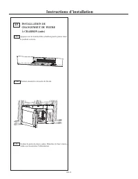
Page 14 - Close the microwave door. Plug in microwave; A5. INSTALLING OR CHANGE; Then close vent's cover
Installation Instructions EN-13 Close the microwave door. Plug in microwave oven or reconnect power. Press the bottom of charcoal filter to place it into the correct position. A5. INSTALLING OR CHANGE THE CHARCOAL FILTER(cont.) A 5.5 A 5.6 A 5.7 Then close vent's cover .
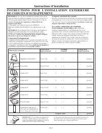
Page 15 - Total Ductwork; Maximum duct length:; INSTALLATION INSTRUCTIONS FOR EXTERNAL EXHAUST DUCTING; diameter duct is acceptable to use.
EQUIVALENT NUMBER EQUIVALENT DUCT PIECES LENGTH x USED = LENGTH Rectangular-to-Round 5 Ft. (1.5 m) x ( ) = Ft. or m Transition Adaptor* Wall Cap 40 Ft. (12.2 m) x ( ) = Ft. or m 90° Elbow 10 Ft. (3 m) x ( ) = Ft. or m 45° Elbow 5 Ft. (1.5 m) x ( ) = Ft. or m 90° Elbow 25 Ft. (7.6 m) x ( ) = Ft. or m...
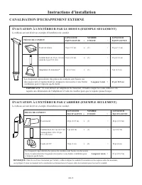
Page 16 - Roof Cap; Wall Cap; Total Length; EXTERNAL EXHAUST DUCTING
EQUIVALENT NUMBER EQUIVALENT DUCT PIECES LENGTH x USED = LENGTH Roof Cap 24 Ft. (7.3 m) x (1) = 24 Ft. (7.3 m) 12 Ft. (3.6 m) Straight Duct 12 Ft. (3.6 m) x (1) = 12 Ft. (3.6 m) (6”/15.2 cm Round) Rectangular-to-Round 5 Ft. (1.5 m) x (1) = 5 Ft. (1.5 m) Transition Adaptor* Equivalent lengths of duct...
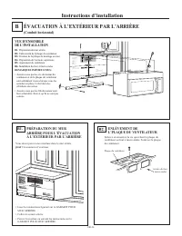
Page 17 - REMOVE BLOWER PLATE
INSTALLATION OVERVIEW B1. Prepare Rear Wall B3. Attach Mounting Plate to Wall B4. Prepare Top Cabinet B5. Adjust Blower B6. Mount the Microwave Oven IMPORTANT NOTES: • Make sure the screws for the blower motor and blower plate are securely tightened when they are reinstalled. This will help to preve...
Page 18 - Roll the blower unit 90°
ATTACH THE MOUNTINGPLATE TO THE WALL B3. • Read the instructions on the TOP CABINETTEMPLATE. • Tape it underneath the top cabinet. • Drill the holes, following the instructions on theTOP CABINET TEMPLATE. CAUTION: Wear safety goggles when drilling holes in the cabinet bottom. Wall Mounting Plate Spa...
Page 19 - Remove the knockout plates in the back of the unit
Attach the exhaust adaptor to the rear of theoven by sliding it into the guides at the topcenter of the back of the oven. AFTER: Fan BladeOpenings Facing Back Place the blower unit back into the opening. Replace the blower plate in the same positionas before with the screw. Make sure the screw is ti...
Page 20 - IMPORTANT: If filler blocks are not; IMPORTANT: Do not grip or use the handle
Attach the microwave oven to the top cabinet. Installation Instructions 3 MOUNT THE MICROWAVEOVEN B6. FOR EASIER INSTALLATION AND PERSONALSAFETY, WE RECOMMEND THAT TWO PEOPLEINSTALL THIS MICROWAVE OVEN. NOTE: If your cabinet is metal, use the nylon grommet around the power cord hole to preventcuttin...
Page 22 - EXHAUST; Place the blower unit back into the opening.; with the top of the unit facing up.
USE TOP CABINET TEMPLATEFOR PREPARATION OF TOPCABINET You need to drill holes for the top support screws, ahole large enough for the power cord to fit through,and a cutout large enough for the exhaust adaptor. • Read the instructions on the TOP CABINET TEMPLATE. • Tape it underneath the top cabinet....
Page 23 - IMPORTANT: If filler blocks are; Exhaust Adaptor; heat shield and door.
3 MOUNT THE MICROWAVEOVEN FOR EASIER INSTALLATION AND PERSONALSAFETY, WE RECOMMEND THAT TWO PEOPLEINSTALL THIS MICROWAVE OVEN. NOTE: If your cabinet is metal, use the nylon grommet around the power cord hole to prevent cutting of the cord. NOTE: We recommend using filler blocks if the cabinet front ...
Page 24 - CONNECTING DUCTWORK; for high temperature applications.
4 Attach the microwave oven to the top cabinet. 8 7 Cabinet Front Cabinet Bottom Shelf Tighten the outer two screws to the top of themicrowave oven. (While tightening screws, holdthe microwave oven in place against the wall andthe top cabinet.) Filler Block Microwave Oven Top Equivalent to Depth of ...
Page 25 - BEFORE YOU USE YOUR MICROWAVE; INST; ring a nd glas s tray in; DDDDDDD; PRODU; Read the; REGIS; U SE; Replace house fuse or turn breaker back on.; FILL OUT PRODUCT R EGISTRATION CAR D
Remove all packing material from the microwave oven. 2. Make sure the microwave oven has beeninstalled according to instructions. 1. BEFORE YOU USE YOUR MICROWAVE Ensure properground existsbefore use INST ALLA TION INSTR UCTIONS 3. D G DDDDDDD Installation Instructions ring a nd glas s tray in cavit...
Page 26 - Printed in China
Printed in China " 2 / 1 - 4 3/8" 3/8" 13-3/8" 2" 2" 12-1/2" 6-1/4" " 2 3 / 7 2 - 9 " 4 / 1 - 4 3/8" 3/8" 3/8" 2" 1/2" 13-3/8" 3/8" TO EDGE ...
Page 27 - Lea estas instrucciones completamente y con atención.; Nota para el consumidor:; Nivel de preparation tecnica:; La instalacion correcta es responsabilidad del instalador.
LEA CUIDADOSAMENTE. CONSERVE ESTAS INSTRUCCIONES. . Lea estas instrucciones completamente y con atención. • • • • Nota para el consumidor: • Nivel de preparation tecnica: • La instalacion correcta es responsabilidad del instalador. • Las fallas del producto que resulten de una instalación incorrecta...
Page 29 - Antes de usar el horno microondas; CONTENIDO; Información general; Instrucciones de instalación; La información de plantilla
Antes de usar el horno microondas CONTENIDO Información general Guía de la instalación paso a paso B A Instrucciones de instalación Recirculación Instalación del horno microondas ........................19 Preparación del gabinete superior .....................17 Montaje de la placa de instalación e...
Page 31 - Tornillos para madera; PIEZA; PIEZAS INCLUIDAS; KIT DE FERRETERÍA; Estante; Param algunos modelos; Param algunos modelos
Tornillos para madera ( " x 2") Tornillos de fiador (y tuercas de mariposa)( " x 3") Tornillos autoalinea-ntes para máquina ( "-28 x3 ") Moldura aislante de nylon (para los gabinetes metálicos) • • • DAÑOS-ENVÍO (TRANSP-ORTE)/INSTALACIÓN Instrucciones de instalación PIEZAS IN...
Page 32 - Si va a instalar el horno microondas debajo de un gabinete plano; espacio libre; AX
HERRAMIENTAS NECESARIAS Instrucciones de instalación • Mètre • scie trépan• Trouveur de goujons ou marteau• Niveau • Ruban adhésif et de masquage • Ciseaux • n #1 tournevis cruciforme• Perceuse électrique• Foret 3/16 ’’, 1/2 ’’, 5/8 ’’• Blocs de bois de remplissage pour armoires à fond encastré• Cis...
Page 33 - Tornillos; Bolsa de accesorios pequeña
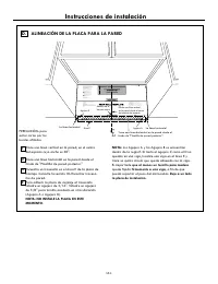
COLOCACIÓN DE LA PLACA DE INSTALACIÓN 1 Instrucciones de instalación 1 LOCALIZACIÓN DE LAS VIGAS DE LA PARED B. A. 2 Vigas de la pared Centro 3 Caja de cartón Tire de la caja de cartón hacia arriba, para separarla del horno. 2 Espuma de poliestireno 3 1 Tornillos Tornillos Placa de instalación 5 4 C...
Page 34 - UBICACIÓN DE LA PLACA PARA LA PARED DE BAJO DEL GABINETE; EL MICROONDAS DEBE QUEDAR NIVELADO.
C . C 3/8" TO EDGE NOTE: IT IS V ERY IMPOR TANT TO READ AND F OLLOW THE DIRECTION S IN ...
Page 35 - ALINEACIÓN DE LA PLACA PARA LA PARED; Los Agujero A y los Agujero B se encuentran; que al menos un tornillo para madera; quede fijado; firmemente a una viga; pueda soportar el peso del microondas.; Deje a un lado
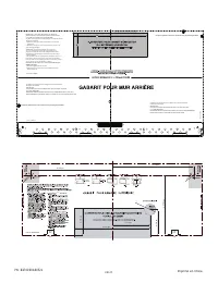
Instrucciones de instalación D. CL 3/8" TO EDGE NOTE: IT IS VERY IMPORTANT TO READ AND FOLLOW THE DIRECTIONS IN THE INSTALLATION INSTRUCTIONS BEFORE PROCEEDING WITH THIS REAR WALL TEMPLATE. This Rear Wall Template serves to position the bottom mounting plate and to locate the horizontal exhaust ...
Page 36 - TIPOS DE INSTALACIÓN; este horno microondas se ha fábricado para un; NOTA: lea las páginas
A TIPOS DE INSTALACIÓN (A Elección Entre A, B o C) Este horno microondas está diseñado para adaptarse a los tres tipos siguientes de ventilación:A. Extracción superior externa (conducto vertical)B. Extracción trasera externa (conducto horizontal)C. Recirculación (sin conducto de extracción) EXTRACCI...
Page 37 - DESCRIPCIÓN GENERAL DE LA INSTALACIÓN; Para utilizar tornillos de fiador:
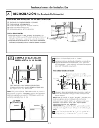
· · Instrucciones de instalación A1. 1 2 A NOTAS IMPORTANTES: RECIRCULACIÓN (Sin Conducto De Extracción) DESCRIPCIÓN GENERAL DE LA INSTALACIÓN C1. Montaje de la placa de instalación en la pared C2. Preparación del gabinete superior C3. Verificación del conjunto del Placa del Ventilador C4. Instalaci...
Page 38 - IMPORTANTE: No agarre ni use la manija o el escudo térmico
Instrucciones de instalación A3. A4. Placa del Ventilador ·· A2. ·· · Lea las instrucciones de la sección PLANTILLA PARA EL GABINETE SUPERIOR.Adhiera con cinta la plantilla al gabinete superior. USO DE LA PLANTILLA PARA EL GABINETE SUPERIOR A FIN DE PREPARAR EL ÁREA DE DICHO GABINETE Es necesario ta...
Page 41 - PIEZAS DEL CONDUCTO; Tapa de salida a la pared; INSTRUCCIONES DE INSTALACIÓN DE CONDUCTOS DE ESCAPE EXTERNAS; Asimismo, asegúrese de que los reguladores de; Largo total del sistema de conductos =; Conexión de escape
= x PIEZAS DEL CONDUCTO Adaptador de unión entre el conducto rectangular y el redondo* Pies o m (metros) = ) ( x 5 pies (1,5 m) Tapa de salida a la pared = ) ( x 10 pies (3 m) ° Codo de 90 = ) ( x 5 pies (1,5m) ° Codo de 45 = ) ( x 25 pies (7,6 m) ° Codo de 90 = ) ( x 5 pies (1,5 m) ° Codo de 45 = )...
Page 42 - EXTRACCIÓN SUPERIOR EXTERNA (SÓLO EJEMPLO); EXTRACCIÓN TRASERA EXTERNA (SÓLO EJEMPLO); CONDUCTOS DE ESCAPE EXTERNAS; Tapa d salida al techo
La siguiente tabla contiene un ejemplo de una posible instalación de un sistema de conducto de extracción. EXTRACCIÓN SUPERIOR EXTERNA (SÓLO EJEMPLO) La siguiente tabla contiene un ejemplo de uno posible instalación de un sistema de conducto de extracción. Instrucciones de instalación EXTRACCIÓN TRA...
Page 43 - EXTRACCIÓN TRASERA EXTERNA
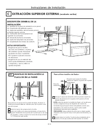
· · Parte trasera del microondas Instrucciones de instalación B1. ·· · B2. B Placa del ventilador 3/8" T O E DGE NO TE : IT IS VE RY IM POR T ANT TO RE AD AND FOL L OW TH E DIR EC TIONS IN T HE IN STA LLATIO N INS TR UCTIO NS BEFO RE PR O C EED ING W ITH TH IS RE AR WALL TEMP LATE . T his Re ar ...
Page 44 - B4. USO DE LA PLANTILLA PARA EL
Instrucciones de instalación B3. ·· · Pared Placa de instalación El espacio que ocupan los tornillos fiadores es superior al grueso de la pared Tornillo fiador Tuercas de mariposa Para utilizar tornillos de fiador: Extremo de tornillo 12 3 4 2 1 B5. Extremo B Extremo A Parte trasera del microondas M...
Page 45 - Retire las placas preperforadas en la parte trasera
Instrucciones de instalación Vuelva a colocar el ventilador dentro de su abertura. B5. Gire el ventilador hacia la izquierda 180 °. Antes del giro Después del giro Antes de la reorientación Después de la reorientación Cables orientados a través del lado derecho Cables orientados a través del lado iz...
Page 47 - EXTRACCIÓN SUPERIOR EXTERNA
3 4 MONTAJE DE INSTALACIÓN LA PLACA DE EN LA PARED C1. 1 Pared Placa de instalación El espacio que ocupan los tornillos fiadores es superior al grueso de la pared Extremo de tornillo Tornillo fiador Tuercas de mariposa Para utilizar tornillos de fiador: Instrucciones de instalación 2 EXTRACCIÓN SUPE...
Page 48 - No tire hacia afuera ni estire los cables
C2. ·· · Instrucciones de instalación C3. Placa del ventilador Tornillo del motor del ventilador Parte trasera del microondas 2 Extremo B Extremo A 1 3 Parte trasera del microondas Antes de girar Después de girar Parte trasera del microondas Parte trasera del microondas Parte trasera del microondas ...
Page 51 - ANTES DE USAR EL HORNO MICROONDAS
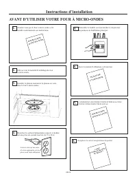
2. 1. ANTES DE USAR EL HORNO MICROONDAS INSTRUCCIONES DE INSTALACIÓN 3. Instrucciones de instalación 4. 7. 6. INSTRUCCIONES DE INSTALACIÓN GUÍA DE USO Y CUID ADO REGISTR O DEL PRODUCT O Lea el manual de use y cuidado. Vuelva a colocar el fusible correspondiente o encienda de nuevo el disyuntor. 5. ....
Page 52 - Impreso en China; PLANTILLA PARA EL GABINETE SUPERIOR
Impreso en China " 2 / 1 - 4 3/8" 13-3/8" 2" 12-1/2" 6-1/4" " 2 3 / 7 2 - 9 " 4 / 1 - 4 3/8" 13-3/8" 3/8" HASTA EL EXTREMO ANCHO MÍNIMO DE 30" REQUERIDO Corte la plantilla ubicada en la pared de atrás a través de la linea de puntos. Corte la plantilla ubicada en ...
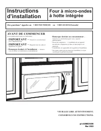
Page 53 - à hotte intégrée; IMPORTANT –; Remarque destinée à l’installateur –; VEUILLEZ LIRE ATTENTIVEMENT.; AVANT DE COMMENCER; Des questions? Appelez au; ou
Instructions d’installation Four à micro-ondes à hotte intégrée Lisez attentivement toutes ces instructions. • IMPORTANT – Conservez ces instructions pour l’inspecteur local. • IMPORTANT – Respectez tous les codes et règlements en vigueur. • Remarque destinée à l’installateur – Assurez- vous de lais...
Page 55 - Instructions d’installation; Renseignements généraux
Instructions d’installation INDEX: Renseignements généraux Guide d’installation étape par étape B Évacuation à l’extérieur par l’arrière ..............................16-19 6-8 Installation de la plaque de montage ...................................... Mesures de sécurité importantes ..................
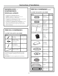
Page 57 - PIÈCES COMPRISES; SACHET DE QUINCAILLERIE
Instructions d’installation DOMMAGES — EXPÉDITION/ INSTALLATION • Si l’appareil est endommagé durant le transport , retournez-le au magasin où vous l’avez acheté pour réparation ou remplacement. • Si l’appareil est endommagé par le client , la réparation ou le remplacement reste à la charge du clien...
Page 58 - DÉGAGEMENTS POUR L’INSTALLATION; i l’évacuation de l’air de votre four à micro; Dosseret
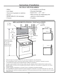
Instructions d’installation OUTILS NÉCESSAIRES • Mètre • scie trépan • Trouveur de goujons ou marteau • Niveau • Ruban adhésif et de masquage • Ciseaux • n #1 tournevis cruciforme • Perceuse électrique • Foret 3/16 ’’, 1/2 ’’, 5/8 ’’ • Blocs de bois de remplissage pour armoires à fond encastré • Cis...
Page 59 - LOCALISATION DES MONTANTS; ENLEVER LE FOUR À MICRO-ONDES
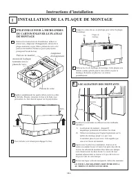
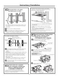
Instructions d’installation INSTALLATION DE LA PLAQUE DE MONTAGE 1 LOCALISATION DES MONTANTS B. Localisez les montants en utilisant une des méthodes suivantes : A. Localisateur de montant – dispositif magnétique permettant de localiser les clous. B. Utilisez un marteau pour frapper légèrement sur la...
Page 60 - ÉTABLISSEMENT DE L’EMPLACEMENT DE LA PLAQUE MURALE SOUS; Emplacement de la plaque - sous une armoire
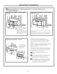
Instructions d’installation Vos armoires peuvent être dotées de garnitures décoratives qui entravent l’installation du micro-ondes. Enlevez l’élément décoratif pour installer convenablement le four à micro-ondes et pour vous assurer qu’il est de niveau. LE FOUR À MICRO-ONDES DOIT ÊTRE DE NIVEAU. Uti...
Page 61 - ALIGNEMENT DE LA PLAQUE MURALE
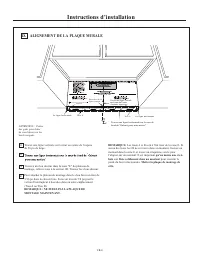
Instructions d’installation 3 2 1 ATTENTION : Portezdes gants pour éviterde vous blesser sur lesbords coupants. ALIGNEMENT DE LA PLAQUE MURALE D. Tracez une ligne horizontale sur le mur de La ligne horizontale La ligne horizontale Trou A Trou B Zone E Encoches de la ligne centrale " " de 30 ...
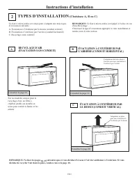
Page 62 - ÉVACUATION À L’EXTÉRIEUR PAR; Consultez la page 20; décidez de recycler l’air dans la pièce, rendez-vous à la page 10.; Consultez la page 10; RECYCLAGE D’AIR; REMARQUE: Ne lisez les pages
Instructions d’installation TYPES D’INSTALLATION (Choisissez A, B ou C) 2 Ce four à micro-ondes est conçu pour s’adapter aux trois types d’évacuation suivants : A. Évacuation à l’extérieur par le dessus (conduit vertical) B. Évacuation à l’extérieur par l’arrière (conduit horizontal) C. Recyclage (s...
Page 63 - FIXATION DE LA PLAQUE; Pour utiliser les boulons à ailettes :
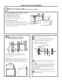
Instructions d’installation RECYCLAGE D’AIR (évacuation sans conduit) A FIXATION DE LA PLAQUE DE MONTAGE AU MUR A1. Placez la plaque de montage contre le mur et insérez les écrous à ailettes dans les trous du mur pour fixer la plaque. REMARQUE: Avant de resserrer les boulons à ailettes et la vis à b...
Page 65 - INSTALLATION DU FOUR
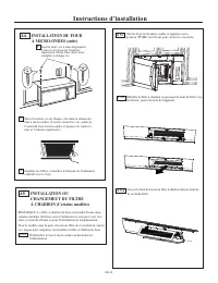
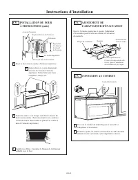
Instructions d’installation INSTALLATION DU FOUR À MICRO-ONDES (suite) A4. Insérez deux vis à auto-alignement à travers les trous de l’armoire supérieure. Faites faire deux tours complets à chaque vis. 5 Serrez les deux vis de chaque côté dans le dessus du four à micro-ondes. (Tout en serrant les vi...
Page 66 - INSTALLATION OU
Instructions d’installation FR-13 A 5.5 Fermez la porte du micro-ondes. Branchez le four à micro- ondes ou reconnectez l'alimentation. A 5.6 A 5.7 Appuyez sur le fond du filtre à charbon pour le placer dans la position correcte. À CHARBON (suite) INSTALLATION OU CHANGEMEUT DU FILTRE A5. Fermez ensui...
Page 67 - Longueur maximale du conduit:; INSTRUCTIONS POUR L`INSTALLATION EXTERIEURE
Instructions d’installation L’évacuation vers l’extérieur requiert un CONDUIT D’ÉVACUATION POUR HOTTE. Lisez attentivement ce qui suit. REMARQUE: Il est important que l’évacuation soit installée en utilisant le chemin le plus direct et avec le moins de coudes possible. Cela assure une bonne évacuati...
Page 68 - CANALISATION D'ECHAPPEMENT EXTERNE; ÉVACUATION À L’EXTÉRIEUR PAR LE DESSUS (EXEMPLE SEULEMENT); ventilation pour n’importe quelle hotte.; ÉVACUATION À L’EXTÉRIEUR PAR L’ARRIÈRE (EXEMPLE SEULEMENT); Le tableau suivant décrit un exemple d’installation de conduit.
Instructions d’installation CANALISATION D'ECHAPPEMENT EXTERNE ÉVACUATION À L’EXTÉRIEUR PAR LE DESSUS (EXEMPLE SEULEMENT) Le tableau suivant décrit un exemple d’installation de conduit. Évent de toiture Conduit droit de 12 pi (3,6 m) (rond de 6 po/15,2 cm) Adaptateur de transition* Les longueurs équ...
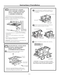
Page 71 - ADAPTATION DU VENTILATEUR; REMARQUE : Les ouvertures de l’ensemble du
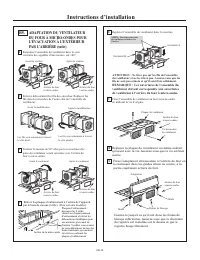
Instructions d’installation ADAPTATION DU VENTILATEUR DU FOUR À MICRO-ONDES POUR L’ÉVACUATION À L’EXTÉRIEUR PAR L’ARRIÈRE (suite) B5. Retournez l’ensemble du ventilateur dans le sens contraire des aiguilles d’une montre, sur 180°. Enlevez délicatement les fils des encoches. Replacez les fils dans le...
Page 72 - IMPORTANT: Si vous n’utilisez pas
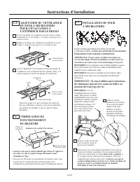
Instructions d’installation INSTALLATION DU FOUR À MICRO-ONDES B6. REMARQU: Lors de l’installation du four à micro- ondes, faites passer le cordon d’alimentation à travers le trou situé dans le fond de l’armoire supérieure. Gardez-le bien serré durant les étapes 1 à 3. Ne coincez pas le cordon ou ne...
Page 73 - VUE D’ENSEMBLE
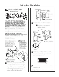
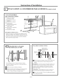
Instructions d’installation ÉVACUATION À L’EXTÉRIEUR PAR LE DESSUS (Conduit vertical) C VUE D’ENSEMBLE DE L’INSTALLATION A1. Fixation de la plaque de montage au mur A2. Préparation de l’armoire supérieure A3. Vérification du fonctionnement du registre A4. Installation du four à micro-ondes A5. Ajust...
Page 74 - orientées vers le haut.
Instructions d’installation UTILISATION DU GABARIT POUR ARMOIRE SUPÉRIEURE POUR LA PRÉPARATION DE L’ARMOIRE SUPÉRIEURE C2. Vous devez percer des trous pour les vis de soutien supérieures, ainsi qu’un trou suffisamment grand pour y faire passer le cordon d’alimentation et une ouverture assez grande p...