Page 2 - MICROWAVE/WALL OVEN COMBINATION INSTALLATION; Microwave Combination; CARPENTRY and SUPPORT; Figure 2: Wall Oven Braces
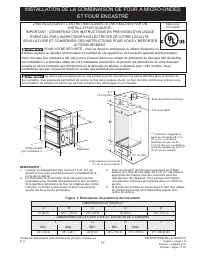
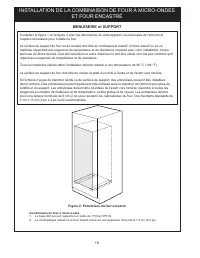
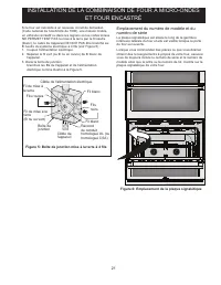
2 MICROWAVE/WALL OVEN COMBINATION INSTALLATION Microwave Combination 1. Base must be capable of supporting 375 pounds (170 kg). 2. Solid plywood or solid wood must be at least ¾” (1.9 cm) thick. CARPENTRY and SUPPORT Refer to Figure 1 or Figure 2 for the dimensions of your appliance and the cabinet ...
Page 3 - Important Notes to the Installer; IMPORTANT SAFETY; Electrical Requirements
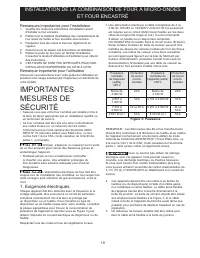
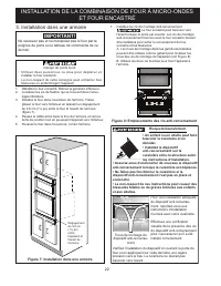
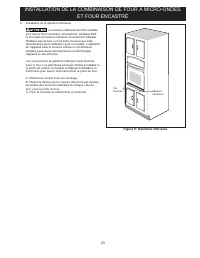
3 MICROWAVE/WALL OVEN COMBINATION INSTALLATION Important Notes to the Installer 1. Read all instructions contained in these installation instructions before installing the wall oven. 2. Remove all packing material from the oven compartments before connecting the electrical supply to the wall oven. 3...
Page 4 - Electrical connection; Electrical Shock Hazard
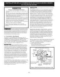
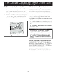
4 MICROWAVE/WALL OVEN COMBINATION INSTALLATION In cold weather shipping and storage conditions, make sure that oven is in final location at least three (3) hours before switching on power. Switching on power while oven is still cold may damage the oven controls. 2. Electrical connection It is the re...
Page 5 - Model and Serial Number Location; Figure 6: Serial Plate Location
5 MICROWAVE/WALL OVEN COMBINATION INSTALLATION Model and Serial Number Location The serial plate is located along the interior side trim of the oven and visible when the door is opened.When ordering parts for or making inquires about your oven, always be sure to include the model and serial numbers ...
Page 6 - Figure 7: Cabinet Installation; Cabinet Installation; Tip Over Hazard
6 MICROWAVE/WALL OVEN COMBINATION INSTALLATION Figure 7: Cabinet Installation 3. Cabinet Installation 1. Unpack the wall oven. Remove the bottom trim. 2. Find the 2 anti-tip mounting screws included in the literature package. 3. Insert the oven into the cabinet opening. Slide oven inward leaving 1½&...
Page 7 - Install the Bottom Trims; Figure 9: Bottom Trim
7 MICROWAVE/WALL OVEN COMBINATION INSTALLATION 2. Install the Bottom Trims Bottom trims must be installed for the oven to function properly. DO NOT operate the oven without bottom oven trims installed. Do not use wood or any other trim that is not manufactured for use with this model. Operating the ...
Page 8 - Checking Operation; Before You Call for Service; Leveling the Wall Oven; the other. Use wood shims under the wall oven to; IMPORTANT NOTE
8 MICROWAVE/WALL OVEN COMBINATION INSTALLATION 5. Checking Operation Your model is equipped with an Electronic Oven Control. Each of the functions has been factory checked before shipping. However, it is suggested that you verify the operation of the electronic oven controls once more. Refer to the ...
Page 9 - INSTALACIÓN DE LA COMBINACIÓN DE HORNO/MICROONDAS; PARA SU SEGURIDAD: No almacene ni use gasolina u otros; Figure 1: Dimensiones del producto y del corte; DIMENSIONES DEL PRODUCTO
9 INSTALACIÓN DE LA COMBINACIÓN DE HORNO/MICROONDAS A B C D E LA INSTALACIÓN Y EL SERVICIO DEBEN SER REALIZADOS POR UN INSTALADOR CALIFICADO. IMPORTANTE: CONSERVE ESTAS INSTRUCCIONES PARA USO DEL INSPECTOR LOCAL DE ELECTRICIDAD. LEA Y CONSERVE ESTAS INSTRUCCIONES PARA CUALQUIER REFERENCIA FUTURA. PA...
Page 10 - ACOPLAMIENTO EN MUEBLE/ESPACIO y ESTRUCTURAS DE APOYO; espacio necesario para colocar el horno.; Figure 2: Soportes de la pared del horno
10 INSTALACIÓN DE LA COMBINACIÓN DE HORNO/MICROONDAS Combinación del microondas 1. La base debe ser capaz de soportar 375 lb (170 kg). 2. La madera contrachapada o la madera maciza debe tener un grosor mínimo de ¾” (1.9 cm). ACOPLAMIENTO EN MUEBLE/ESPACIO y ESTRUCTURAS DE APOYO Consulte la figura 1 ...
Page 11 - Notas importantes para el instalador; INSTRUCCIONES; Requisitos eléctricos
11 INSTALACIÓN DE LA COMBINACIÓN DE HORNO/MICROONDAS Notas importantes para el instalador 1. Antes de instalar el horno de pared, lea todas estas instrucciones de instalación. 2. Antes de conectar el suministro de electricidad al horno de pared, retire todo el material de empaque de los compartimien...
Page 12 - Conexión eléctrica; Riesgo de choque eléctrico; Figure 4: Caja de empalme de conexión a tierra de; negros
12 INSTALACIÓN DE LA COMBINACIÓN DE HORNO/MICROONDAS Para el envío y el almacenamiento en climas fríos, asegúrese de que el horno se encuentre en su ubicación final al menos tres (3) horas antes de encender la energía. Encender la energía cuando el horno aún está frío podría dañar los controles del ...
Page 13 - Ubicación de la placa de número de modelo y; Figure 6: Ubicación de la placa de serie
13 INSTALACIÓN DE LA COMBINACIÓN DE HORNO/MICROONDAS Ubicación de la placa de número de modelo y de serie La placa de serie se ubica a lo largo de la moldura lateral interior del horno y está visible cuando la puerta está abierta.Para realizar pedidos de piezas o realizar consultas sobre el horno, a...
Page 14 - Figure 7: Instalación en el mueble; Instalación en el mueble; IMPORTANTE; No levante ni manipule el horno por la manija de la; Figure 8: Ubicaciones de los tornillos antivuelco; Riesgo de volcamiento
14 INSTALACIÓN DE LA COMBINACIÓN DE HORNO/MICROONDAS 1. Instale los tornillos de montaje antivuelco El horno de pared puede volcarse cuando la puerta está abierta. Se deben instalar los tornillos de montaje antivuelco proporcionados con el horno de pared para evitar el vuelco del horno de pared y le...
Page 15 - Figure 9: Ajuste inferior
15 INSTALACIÓN DE LA COMBINACIÓN DE HORNO/MICROONDAS 2. Instale la moldura inferior La guarda de seguridad inferior debe ser propiamente instalada para que el aparato electrodoméstico funcióne correctamente. No operar el horno sin la guarda de seguridad instalada. No usar guardas fabricadas de mader...
Page 16 - Verificación del funcionamiento; Antes de solicitar servicio técnico; Nivelación del horno de pared; Figure 10: Nivelación
16 INSTALACIÓN DE LA COMBINACIÓN DE HORNO/MICROONDAS 5. Verificación del funcionamiento Su modelo viene equipado con un control de horno electrónico. Cada una de las funciones se han verificado en la fábrica antes del envío. Sin embargo, se sugiere que verifique una vez más el funcionamiento de los ...
Page 17 - L'INSTALLATION ET L'ENTRETIEN DOIVENT ÊTRE RÉALISÉS PAR UN; Figure 1: Dimensions du produit et de l'ouverture; DIMENSIONS DU PRODUIT
17 INSTALLATION DE LA COMBINAISON DE FOUR À MICRO-ONDES ET FOUR ENCASTRÉ A B C D E L'INSTALLATION ET L'ENTRETIEN DOIVENT ÊTRE RÉALISÉS PAR UN INSTALLATEUR QUALIFIÉ. IMPORTANT : CONSERVEZ CES INSTRUCTIONS EN PRÉVISION D'UN USAGE ÉVENTUEL PAR L'INSPECTEUR EN ÉLECTRICITÉ DE VOTRE LOCALITÉ. VEUILLEZ LIR...
Page 18 - MENUISERIE et SUPPORT; l'espace nécessaire pour installer le four.; Figure 2: Entretoises du four encastré
18 INSTALLATION DE LA COMBINAISON DE FOUR À MICRO-ONDES ET FOUR ENCASTRÉ Combinaison de four à micro-ondes 1. La base doit pouvoir supporter un poids de 170 kg (375 lb). 2. Le contreplaqué massif ou le bois massif doit avoir une épaisseur d'au moins 1,9 cm (3/4 po). MENUISERIE et SUPPORT Consultez l...
Page 19 - Remarques importantes pour l'installateur; IMPORTANTES; Exigences électriques
19 INSTALLATION DE LA COMBINAISON DE FOUR À MICRO-ONDES ET FOUR ENCASTRÉ Remarques importantes pour l'installateur 1. Veuillez lire toutes les instructions d'installation avant d'installer le four encastré. 2. Retirez tout le matériel d'emballage des compartiments du four avant de mettre le four enc...
Page 20 - Connexion électrique; Risque de décharge électrique; Boîte de jonction mise à la terre à 3 fils; Fils
20 INSTALLATION DE LA COMBINAISON DE FOUR À MICRO-ONDES ET FOUR ENCASTRÉ Dans des conditions de température froide lors de la livraison et de l'entreposage, assurez-vous que le four repose dans son emplacement final au moins trois (3) heures avant de le mettre sous tension. Si vous mettez le four so...
Page 21 - Emplacement du numéro de modèle et du; Figure 6: Emplacement de la plaque signalétique
21 INSTALLATION DE LA COMBINAISON DE FOUR À MICRO-ONDES ET FOUR ENCASTRÉ Emplacement du numéro de modèle et du numéro de série La plaque signalétique est située le long de la garniture intérieure latérale du four et elle est visible lorsque la porte du four est ouverte. Lorsque vous commandez des pi...
Page 22 - Figure 7: Installation dans une armoire; Installation dans une armoire; Ne soulevez pas et ne manipulez pas le four par la; Figure 8: Emplacements des vis anti-renversement
22 INSTALLATION DE LA COMBINAISON DE FOUR À MICRO-ONDES ET FOUR ENCASTRÉ 1. Installez les vis de montage anti-renversement. Le four encastré peut basculer vers l'avant lorsque la porte est ouverte. Les vis de montage anti-renversement fournies avec le four encastré doivent être installées pour évite...
Page 23 - Figure 9: Garniture inférieure
23 INSTALLATION DE LA COMBINAISON DE FOUR À MICRO-ONDES ET FOUR ENCASTRÉ Figure 9: Garniture inférieure 2. Installation de la garniture inférieure La moulure inférieure doit être installée pour que le four fonctionne correctement. N'utilisez PAS le four sans la moulure inférieure correctement instal...
Page 24 - Vérification du fonctionnement; Avant de faire appel au service après-vente; Mise à niveau du four encastré; Figure 10: Mise à niveau
24 INSTALLATION DE LA COMBINAISON DE FOUR À MICRO-ONDES ET FOUR ENCASTRÉ 5. Vérification du fonctionnement Votre modèle est muni d'un régulateur électronique de four. Chaque fonction a été vérifiée en usine avant la livraison. Toutefois, nous vous recommandons de vérifier une autre fois le fonctionn...