Page 2 - LIMITED WARRANTY AND LIMITATION OF LIABILITY; Fluke Corporation
LIMITED WARRANTY AND LIMITATION OF LIABILITY This Fluke product will be free from defects in material and workmanship for three years from the date of purchase. This warranty does not cover fuses, disposable batteries, or damage from accident, neglect, misuse, alteration, contamination, or abnormal ...
Page 3 - Introduction; XW; Warning; How to Contact Fluke; To register your product, visit
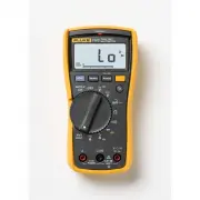
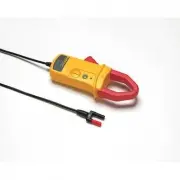
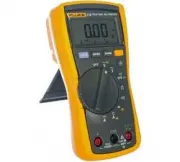
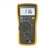
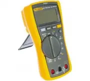
1 Introduction The Fluke 233 (hereafter the Meter) is a compact and easy to operate tool for electrical and electronic circuit measurements. XW Warning Read "Safety Information" before you use the Meter. How to Contact Fluke Use one of the telephone numbers below to speak with a Fluke repres...
Page 4 - Getting Started Manual; Safety Information
233 Getting Started Manual 2 Safety Information The Meter complies with: • ISA-82.02.01 • CAN/CSA C22.2 No. 61010-1-04 • ANSI/UL 61010-1:2004 • EN 61010-1:2001 • EN 61326-1:2006 • EN 61326-2-2:2006 • ETSI EN 300 328 V1.7.1:2006 • ETSI EN 300 489 V1.8.1:2008 • FCC Part 15 Subpart C Sections 15.207, 1...
Page 5 - Do not use the Meter around explosive
True-rms Remote Display Digital Multimeter Safety Information 3 • Remove the test leads from the Meter before the battery door on the Meter base is opened. • Examine the test leads for damaged insulation or exposed metal. Measure the test leads for continuity. Replace damaged test leads before you u...
Page 6 - Caution
233 Getting Started Manual 4 • Use only specified 1.5-V AA batteries (three in the Meter base and two in the display), correctly installed, for Meter power. • Comply with local and national safety requirements when in hazardous locations. • Only use test leads that have the same voltage, category, a...
Page 7 - Table 1. Electrical Symbols; CAT
True-rms Remote Display Digital Multimeter Safety Information 5 Table 1. Electrical Symbols B AC (Alternating Current) J Earth ground F DC (Direct Current) I Fuse X Hazardous voltage P Conforms to European Union directives. W Risk of Danger. Important information. See Manual. ) Conforms to relevant ...
Page 8 - Features; Indication; MIN MAX AVG mode on.
233 Getting Started Manual 6 Features See Tables 3 through 4 for a list of Meter features with a short feature description. Table 2. Display meter remote Auto RangeManual Range 1 2 3 4 5 6 8 9 11 13 12 14 10 7 gcc101.eps No. Symbol Indication 1 MIN MAX AVG mode on. 2 MAX MIN AVG Maximum, minimum, ...
Page 10 - Description; Input for 0 A to 10.00 A current measurements.; COM; Common terminal for all measurements.
233 Getting Started Manual 8 Table 3. Inputs 1 2 3 gcc110.eps No. Terminal Description 1 A Input for 0 A to 10.00 A current measurements. 2 COM Common terminal for all measurements. 3 Input for voltage, continuity, resistance, diode, capacitance, temperature, and frequency measurements.
Page 11 - Continuity beeper turns on at
True-rms Remote Display Digital Multimeter Features 9 Table 4. Function Switch Positions Switch Position Description Hz (button) AC voltage from 0.06 to 1000 V. Frequency from 5 Hz to 50 kHz. DC voltage from 0.001 V to 1000 V. AC voltage from 6.0 to 600.0 mV, dc-coupled. DC voltage from 0.1 to...
Page 12 - Error Messages; Table 5. Error Messages; Internal error. The Meter must be repaired before it will operate.
233 Getting Started Manual 10 Error Messages Table 5 contains possible error messages and the steps to clear the error. Table 5. Error Messages Error Messages Display-module batteries must be replaced before the Meter will operate. Meter-base batteries must be replaced before the...
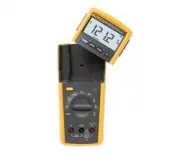
Page 13 - Remote Operation; Figure 1. Display Module Separation
True-rms Remote Display Digital Multimeter Remote Operation 11 Remote Operation 2 1 gcc114.eps Figure 1. Display Module Separation 2 1 gcc115.eps Figure 2. Dock Display Module with Meter Base
Page 14 - Fuse Test; Figure 4. Display-Module Battery Removal
233 Getting Started Manual 12 Fuse Test Good fuse: 0.0 Ω to 0.5 Ω Replace fuse: OL gcc105.eps Figure 3. Fuse Test Battery Replacement 2 3 gcc111.eps Figure 4. Display-Module Battery Removal
Page 15 - Figure 5. Meter Base Battery Replacement
True-rms Remote Display Digital Multimeter Battery Replacement 13 2 1 3 4 gcc112.eps Figure 5. Meter Base Battery Replacement
Page 16 - General Specifications
233 Getting Started Manual 14 General Specifications Maximum voltage between any terminal and earth ground ........................................... 1000 V rms W Fuse for A inputs ..................................................... 11 A, 1000 V 17000A interrupt rating Fuse Altitude Operating ......