Page 2 - Safety Information; XW; Warnings and Precautions; Do not use the Meter around explosive gas or vapor.
114, 115, 116, and 117 Calibration Information 2 Safety Information "Warning" and "Caution" Statements A “ XW Warning" identifies hazardous conditions and actions that could cause bodily harm or death. A " W Caution" identifies conditions and actions that could damage the...
Page 3 - International Electrical Symbols; Table 1. Electrical Symbols; Fuse; Specifications
Digital Multimeters International Electrical Symbols 3 International Electrical Symbols Table 1 lists the international symbols that appear in this document and on the Meter. Table 1. Electrical Symbols Symbol Description Symbol Description B AC (Alternating Current) I Fuse F DC (Direct Current) T D...
Page 4 - Accuracy Specifications
114, 115, 116, and 117 Calibration Information 4 Accuracy Specifications Function Range Resolution Accuracy ± ([% of Reading] + [Counts]) Model [1] DC millivolts 600.0 mV 0.1 mV 0.5 % + 2 114, 115, 116, 117 DC Volts 6.000 V 60.00 V 600.0 V 0.001 V 0.01 V 0.1 V 0.5 % + 2 114, 115, 116, 117 DC, 45 to ...
Page 5 - Input Characteristics; Basic Maintenance; Set the rotary switch to
Digital Multimeters Basic Maintenance 5 Accuracy Specifications (cont) Function Range Resolution Accuracy ± ([% of Reading] + [Counts]) Model [1] Hz (V or A input) [3] 99.99 Hz 999.9 Hz 9.999 kHz 50.00 kHz 0.01 Hz 0.1 Hz 0.001 kHz 0.01 kHz 0.1 % + 2 115, 116, 117 Notes: [1] Models listed in this col...
Page 6 - OK; Figure 1. Fuse Testing; Replacing the Battery and Fuse; Warning; Figure 2. Battery and Fuse Replacement
114, 115, 116, and 117 Calibration Information 6 HOLD MIN MA X RANGE 10 A FUSED COM V A Lo / H OF F Hz Hz AUT O-V LoZ V o l t A l e r t A A V V mV Vo ltAle r t TRUE RMS MU LTIMETER 117 <.5 OK OK erc010f.emf Figure 1. Fuse Testing Replacing the Battery and Fuse XW Warning To avoid shock, injury, o...
Page 7 - Remove the Meter from its holster.; Performance Tests; Required Equipment; Table 2. Required Equipment; DC Volts
Digital Multimeters Performance Tests 7 2. Remove the Meter from its holster. 3. Remove two screws from the case bottom. 4. Separate the case bottom from the case top. 5. Remove the fuse from its holder and replace with an 11 A, 1000 V, FAST fuse having a minimum interrupt rating of 17,000 A. Use on...
Page 8 - Double Banana plug; Testing the Display; Figure 3. Display Segments; Backlight Test; Off; Preparing for the Performance Tests; To avoid possible electric shock or personal injury:
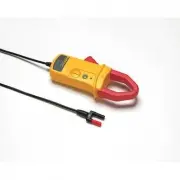
114, 115, 116, and 117 Calibration Information 8 Table 2. Required Equipment (cont) Recommended Equipment Measurement Function Accuracy 5500A Multi-product Calibrator (or equivalent) Frequency (115, 116, and 117) 2 V, 50 kHz ± 0.025 % Fluke 80 AK K-type Thermocouple Adapter Accessory Temperature (11...
Page 9 - Warm up the calibrator as required by its specifications.; Table 3. DMM Performance Tests
Digital Multimeters Performance Tests 9 2. Warm up the calibrator as required by its specifications. 3. Allow the temperature of the UUT to stabilize at room temperature (23 ° C ± 5 ° C [73 ° F ± 9 ° F] ). 4. Check the fuses and Battery, and replace them if necessary. Refer to “Testing the Fuses”, a...
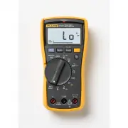
Page 11 - Display Reading; Lo; Testing the VoltAlert Function (117 only)
Digital Multimeters Performance Tests 11 Table 3. DMM Performance Tests (cont) Display Reading Step Function Range Applied 114 [1] 115 [1] 116 [1] 117 [1] 41 VoltAlert Hi N/A N/A N/A Refer to steps 1 – 5 in the procedure below 42 VoltAlert Lo N/A N/A N/A Refer to steps 6 – 9 in the procedure below [...
Page 12 - Center Meter top on Hi terminal.; Figure 4. VoltAlert Testing; Calibration Adjustment; ZCAL; Calibration Adjustment Password; OFF; ZCAL
114, 115, 116, and 117 Calibration Information 12 STBY 7 8 2 5 0 +/- 4 . . SCOPE OUT TRIG AUX A SENSE A U X V NORMAL V RTD TR U E R M S M U LT IM E TE R 11 7 V o ltA le rt Center Meter top on Hi terminal. Note that LED is RED Insert Double Banana erc013f.emf Figure 4. VoltAlert Testing 8. Hold the M...
Page 13 - Restoring the Default Password; Short S7 to reset to Default password; Figure 5. Calibration Password Reset
Digital Multimeters Calibration Adjustment 13 2. Press g once to see the calibration counter. 3. Press g again to start the password entry. The Meter displays “ ?>>> ” 4. The Meter buttons indicated below represent the numbers 1 through 5 when entering or changing the password: K = 1 M = 2 ...
Page 15 - Notes
Digital Multimeters Calibration Adjustment 15 Notes Set the calibrator to Standby prior to changing the function switch position and after completing adjustment of each function. If the calibration adjustment procedure is not properly completed, the Meter will not operate correctly. Table 4. Calibra...
Page 17 - Replacement Parts; Table 5 lists the Meter’s replacable parts identified in Figure 6.; Figure 6. Exploded View of Meter
Digital Multimeters Replacement Parts 17 Replacement Parts Table 5 lists the Meter’s replacable parts identified in Figure 6. 6 12 10 23 20 17 21 9 7 5 8 1 3 4 2 11 15 4 PL 2 PL 13 19 14 18 22 16 erc14.emf Figure 6. Exploded View of Meter
Page 19 - Table 5. Replaceable Parts List; MANUAL,116C USERS MANUAL; Warranty
Digital Multimeters Warranty 19 Table 5. Replaceable Parts List Item Description Part Number Qty. 19 BATTERY,PRIMARY,MNO2-ZN,9V,505MAH,6LR61,ALKALINE, 17X26X48MM,BULK 614487 1 20 FLUKE 12-8004,SHOCK ABSORBER 878983 1 FLUKE-117-2005,TILT STAND 2525594 1 21 FLUKE-117-2005,TILT STAND, 11X China 2631071...