Faber LITHOS CONCRETE - Manuals
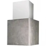
User Manual Faber LITHOS CONCRETE
Summary
3 3 IÇERIKLER TAVSIYELER VE ÖNERILER.............................................................................................................................................. 64 ÖZELLIKLER...............................................................................................................
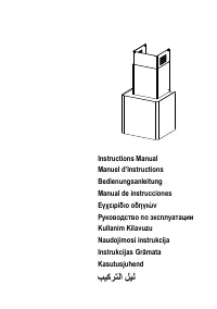
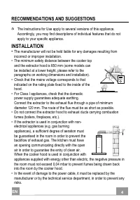
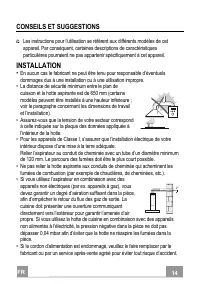
EN 4 4 RECOMMENDATIONS AND SUGGESTIONS The Instructions for Use apply to several versions of this appliance. Accordingly, you may find descriptions of individual features that do not apply to your specific appliance. INSTALLATION • The manufacturer will not be held liable for any damages resulting f...
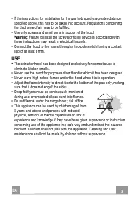
EN 5 5 • If the instructions for installation for the gas hob specify a greater distance specified above, this has to be taken into account. Regulations concerning the discharge of air have to be fulfilled. • Use only screws and small parts in support of the hood. Warning : Failure to install the sc...
Faber Range Hoods Manuals
-
 Faber 110.0338.674
User Manual
Faber 110.0338.674
User Manual
-
 Faber 110.0338.675
User Manual
Faber 110.0338.675
User Manual
-
 Faber 110.0389.223
User Manual
Faber 110.0389.223
User Manual
-
 Faber 741 BASE BK A60
User Manual
Faber 741 BASE BK A60
User Manual
-
 Faber 741 BASE BK A60 EXP
User Manual
Faber 741 BASE BK A60 EXP
User Manual
-
 Faber 741 BASE W A50
User Manual
Faber 741 BASE W A50
User Manual
-
 Faber 741 BASE W A50 FB EXP
User Manual
Faber 741 BASE W A50 FB EXP
User Manual
-
 Faber 741 BASE W A60
User Manual
Faber 741 BASE W A60
User Manual
-
 Faber 741 BASE X A50
User Manual
Faber 741 BASE X A50
User Manual
-
 Faber 741 BASE X A50 FB EXP
User Manual
Faber 741 BASE X A50 FB EXP
User Manual
-
 Faber 741 BASE X A60
User Manual
Faber 741 BASE X A60
User Manual
-
 Faber 741 BASE X A60 FB EXP
User Manual
Faber 741 BASE X A60 FB EXP
User Manual
-
 Faber 741 PB W A50
User Manual
Faber 741 PB W A50
User Manual
-
 Faber 741 PB W A50 300.0557.512
User Manual
Faber 741 PB W A50 300.0557.512
User Manual
-
 Faber 741 PB W A60
User Manual
Faber 741 PB W A60
User Manual
-
 Faber 741 PB W A60 300.0557.513
User Manual
Faber 741 PB W A60 300.0557.513
User Manual
-
 Faber 741 PB X A50
User Manual
Faber 741 PB X A50
User Manual
-
 Faber 741 PB X A50 300.0557.514
User Manual
Faber 741 PB X A50 300.0557.514
User Manual
-
 Faber 741 PB X A60
User Manual
Faber 741 PB X A60
User Manual
-
 Faber 741 PB X A60 300.0557.515
User Manual
Faber 741 PB X A60 300.0557.515
User Manual