Page 2 - Welcome
Welcome Congratulations on purchasing your new air conditioner. The Esatto brand is proudly distributed within Australia by Residentia Group Pty Ltd. Please refer to the warranty card at the rear of this manual for information regarding your product’s parts and labour warranty, or visit us online at...
Page 3 - Contents
Page 5 Safety Precautions Page 9 Unit Specifications & Features Page 14 Care & Maintenance Page 16 Troubleshooting Page 19 Accessories Page 20 Installation Summary (Indoor) Page 21 Unit Parts Page 22 Indoor Unit Installation Page 28 Outdoor Unit Installation Page 32 Refrigerant Piping Connec...
Page 4 - Read Safety Precautions Before Operation and Installation; or; CAUTION; EN Standard requirements; WARNINGS FOR PRODUCT USE; Do not; the fan may be rotating at high speeds.; collect around the unit and cause explosion.; Do not; Safety Precautions; Do not; Page 3; WARNING; This symbol indicates the possibility; CAUTION; This symbol indicates the possibility of; This page
4 Safety Precautions Safety Read Safety Precautions Before Operation and Installation The seriousness of potential damage or injuries is classified as either a WARNING or CAUTION . Incorrect installation due to ignoring instructions can cause serious damage or injury. WARNING This appliance can be u...
Page 6 - Page 4; CLEANING AND MAINTENANCE WARNINGS; Page 5; WARNINGS FOR PRODUCT INSTALLATION; do not; the
6 Safety Precautions Page 4 • Do not clean the air conditioner with combustible cleaning agents. Combustible cleaning agents can cause fire or deformation. CLEANING AND MAINTENANCE WARNINGS • Turn off the device and disconnect the power before cleaning. Failure to do so can cause electrical shoc...
Page 8 - Page 6; WARNING for Using R32/R290 Refrigerant; UL; IEC; Standard Requirements); European Disposal Guidelines; C o rrect D isp o sal o f T h is Pro d u ct; Page 7; Unit Specifications and Features; Indoor unit display; Display Code
8 Safety Precautions Page 6 WARNING for Using R32/R290 Refrigerant 2 2 2 2 2 2 When flammable refrigerant are employed, appliance shall be stored in a well -ventilated area where the room size corresponds to the room area as specifiec for operation.For R32 frigerant models:Appliance shall be ins...
Page 10 - Page 8; Page 9; Operating temperature; To further optimize the performance of your unit, do the following:; Keep doors and windows closed.; Inverter Split Type; When outside
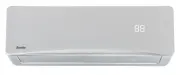
10 Unit Specifications and Featu res Page 8 (E) Power Cable (Some Units ) Remote Control Remote Control Holder (Some Units) Functional Filter (On Back of Main Filter - Some Units) Louver Front Panel Display window Display window The unit has a build-in light sensor to detect the ambient brightne...
Page 12 - Other Features; SLEEP; Not all; Setting vertical angle of air flow; NOTE ON LOUVER ANGLES; Do not put your fingers in or near the blower; Deflector
12 Page 10 Unit Specifications and Featu res Other Features • Auto-Restart(some units) If the unit loses power, it will automatically restart with the prior settings once power has been restored. • Anti-mildew (some units) When turning off the unit from COOL, AUTO (COOL), or DRY modes, the air c...
Page 14 - Care and Maintenance; button
14 Page 12 Cleaning Your Indoor Unit BEFORE CLEANING OR MAINTENANCE ALWAYS TURN OFF YOUR AIR CONDITIONERSYSTEM AND DISCONNECT ITS POWER SUPPLYBEFORE CLEANING OR MAINTENANCE. CAUTION Only use a soft, dry cloth to wipe the unit clean. If the unit is especially dirty, you can use a cloth soaked in ...
Page 16 - Common Issues; The power cord is damaged or abnormally warm; Troubleshooting
16 Page 14 Common Issues The following problems are not a malfunction and in most situations will not require repairs. Issue Possible Causes Unit does not turn on when pressingON/OFF button The Unit has a 3-minute protection feature that prevents the unit from overloading. The unit cannot be res...
Page 18 - Problem
18 Page 16 Tr oubleshooting Problem Possible Causes Solution The unit is notworking Power failure Wait for the power to be restored The power is turned off Turn on the power The fuse is burned out Replace the fuse Remote control batteries are dead Replace batteries The Unit’s 3-minute protection...
Page 20 - Installation Summary - Indoor Unit; NOTE ON ILLUSTRATIONS; Unit Parts
20 Page 18 Installation Summary -Indoor Unit Installation Summary - Indoor Unit Select Installation Location Attach Mounting Plate Determine Wall Hole Position 1 2 3 Drill Wall Hole 4 12cm (4.75in) 2.3m (90.55in) 12cm (4.75in) 15cm (5.9in) Mount Indoor Unit STEP 8 Wrap Piping and Cable(not appli...
Page 22 - DO NOT; install unit in the following; NOTE FOR CONCRETE OR BRICK WALLS:; Indoor Unit Installation; When drilling the wall hole, make sure to; Type A
22 Page 20 Indoor Unit Installation Installation Instructions – Indoor unit PRIOR TO INSTALLATION Before installing the indoor unit, refer to the label on the product box to make sure that the model number of the indoor unit matches the model number of the outdoor unit. Step 1: Select installati...
Page 24 - Step 4: Prepare refrigerant piping; Based on the position of the wall hole relative; NOTE ON PIPING ANGLE; PLUG THE UNUSED DRAIN HOLE; Rated Current of
24 Page 22 Indoor Unit Installation Step 4: Prepare refrigerant piping The refrigerant piping is inside an insulating sleeve attached to the back of the unit. You must prepare the piping before passing it through the hole in the wall. 1. Based on the position of the wall hole relative to the mou...
Page 26 - DO NOT MIX UP LIVE AND NULL WIRES; This is dangerous, and can cause the air; NOTE ABOUT WIRING
26 Page 24 Indoor Unit Installation 1. O pen front panel of the indoor unit. 2. Using a screwdriver, open the wire box cover on the right side of the unit. This will reveal the terminal block. Terminal block Wire cover Screw Cable clamp WARNING 3. Unscrew the cable clamp below the terminal block...
Page 28 - Outdoor Unit Installation; Insert the drain joint into the hole in the base; seal; Air inlet
28 Outdoor Unit Installation Page 26 Installation ev o ba ) ni 42 ( mc 06 60cm (24in) on righ t 30cm (12in) on left 200cm (79in) in fron t 30cm (12in) from back wall Installation Instructions – Outdoor unit Step 1: Select installation location Before installing the outdoor unit, you must choose ...
Page 30 - W x H x D; PAY
30 Page 28 Outdoor Unit Installation If you will install the unit on a wall-mounted bracket , do the following: 1.Mark the position of bracket holes based on dimensions chart. 2. Pre-drill the holes for the expansion bolts. 3. Place a washer and nut on the end of each expansion bolt. 4. Thread e...
Page 32 - When connecting refrigerant piping,; let substances or gases other than the specified; Model; Refrigerant Piping Connection; Step 4: Connect pipes; MINIMUM BEND RADIUS; Step 3: Flare pipe ends; PIPING EXTENSION BEYOND FLARE FORM; Outer Diameter of
32 Page 30 Note on Pipe Length The length of refrigerant piping will affect the performance and energy efficiency of the unit. Nominal efficiency is tested on units with a pipe length of 5 meters (16.5ft). A minimum pipe run of 3 metres is required to minimise vibration & excessive noise.In ...
Page 34 - Torque Requirements; Instructions for Connecting Piping to Outdoor Unit; TORQUE REQUIREMENTS; DO NOT USE EXCESSIVE TORQUE; torque requirements shown in the table above.; Preparations and Precautions; BEFORE PERFORMING EVACUATION; Evacuation Instructions; OPEN VALVE STEMS GENTLY; Air Evacuation
34 Page 32 Refrigerant piping Connection 2. Tighten the flare nut as tightly as possible by hand. 3. Using a spanner, grip the nut on the unit tubing. 4. While firmly gripping the nut on the unit tubing, use a torque wrench to tighten the flare nut according to the torque values in the Torque Re...
Page 36 - Note on Adding Refrigerant; mix refrigerant types.; ADDITIONAL REFRIGERANT PER PIPE LENGTH; Electrical Safety Checks; Electrical and Gas Leak Checks
36 Page 34 Air Evacuation Note on Adding Refrigerant Some systems require additional charging depending on pipe lengths. The standard pipe length variesaccording to local regulations. For example, in North America, the standard pipe length is 7.5m (25’).In other areas, the standard pipe length i...
Page 38 - Test Run Instructions; Test Run
38 Page 36 Test Run Test Run Instructions You should perform the Test Run for at least 30 minutes. 1. Connect power to the unit. 2. Press the ON/OFF button on the remote controller to turn it on. 3. Press the MODE button to scroll through the following functions, one at a time: • COOL – Select l...
Page 40 - Purchase Details
40 Purchase Details For your records, please record details of your purchase below and staple your receipt on the opposite page. Your serial number can be found on the Rating Label which is applied to your unit. S TO R E D E TA I L S STORE NAME | ADDRESS | TELEPHONE | PURCHASE DATE | P R O D U C T D...
Page 41 - Attach your receipt to this page
Page 42 - Warranty Information
42 WARRANTY TERMS AND CONDITIONSAIR-CONDITIONING This document sets out the terms and conditions of the product warranties for Residentia Group Appliances. It is an important document. Please keep it with your proof of purchase documents in a safe place for future reference should you require servic...
Page 44 - A R E S I D E N T I A
This page is intentionally left blank Appliances Exactly what you need A R E S I D E N T I A G R O U P I N I T I AT I V E