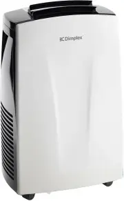
Page 2 - IMPORTANT; THESE INSTRUCTIONS SHOULD BE READ CAREFULLY AND; Note also the information presented on the appliance
IMPORTANT THESE INSTRUCTIONS SHOULD BE READ CAREFULLY AND RETAINED FOR FUTURE REFERENCE. Note also the information presented on the appliance CAUTION: FAILURE TO FOLLOW THESE INSTRUCTIONS MAY CAUSE INJURY AND/OR DAMAGE AND MAY INVALIDATE YOUR WARRANTY Please read the operating instructions carefully...
Page 3 - may lead to a risk of fire or electric shock.; WARNING; drop or insert any object or fingers into any openings.; ON
may lead to a risk of fire or electric shock. • Only operate this appliance with a minimum of 50cm clearance all around i.e. away from walls, furniture and overhanging objects such as curtains or a shelf. • WARNING : To avoid danger of suffocation please remove all packaging materials particularly p...
Page 4 - CAUTION: RISK OF FIRE/FLAMMABLE MATERIALS. THE APPLIANCE MUST BE; room size corresponds to the room area as specified for operation.
WARNING: For using R290 refrigerant. ThIs symbol shows that this appliance uses a flammable refrigerant. If the refrigerant is leaked and exposed to an external ignition source, there is a risk of fire. CAUTION: RISK OF FIRE/FLAMMABLE MATERIALS. THE APPLIANCE MUST BE INSTALLED, USED & STORED IN ...
Page 5 - Presence of fire extinguisher; No Smoking signs shall be displayed.
1. Transport of equipment containing flammable refrigerants - see transport regulations 2. Marking of equipment using signs - see local regulations 3. Disposal of equipment using flammable refrigerants - see national regulations. 4. Storage of equipment/appliances - The storage of equipment should b...
Page 6 - Checks to the refrigeration equipment; installations using flammable refrigerants:; Checks to electrical devices; Initial safety checks shall include:; Repairs to sealed components; isolated prior to working on them.
• Checks to the refrigeration equipment Where electrical components are being changed, they shall be fit for the purpose and to the correct specification. At all times the manufacturer's maintenance and service guidelines shall be followed. If in doubt consult the manufacturer's technical department...
Page 7 - Repair to intrinsically safe components; in the atmosphere from a leak.; Cabling; such as compressors or fans.; Detection of flammable refrigerants; detector using a naked flame) shall not be used.; Leak detection methods; ignition sources and there is ventilation available.
• Repair to intrinsically safe components Do not apply any permanent inductive or capacitance loads to the circuit without ensuring that this will not exceed the permissible voltage and current permitted for the equipment in use. Intrinsically safe components are the only types that can be worked on...
Page 8 - Charging procedures; minimise the amount of refrigerant contained in them.; Decommissioning; a) Become familiar with the equipment and its operation.; Labelling
• Charging procedures In addition to conventional charging procedures, the following requirements shall be followed. Ensure that contamination of different refrigerants does not occur when using charging equipment. Hoses or lines shall be as short as possible to minimise the amount of refrigerant co...
Page 9 - Recovery; When removing refrigerant from a system, either for servicing or
• Recovery When removing refrigerant from a system, either for servicing or decommissioning, it is recommended good practice that all refrigerants are removed safely. When transferring refrigerant into cylinders, ensure that only appropriate refrigerant recovery cylinders are employed. Ensure that t...
Page 11 - Specification
Model no. DCPAC07C Colour White Power supply 220-240V~, 50Hz Operating temperature 18-35°C Thermostat range 18-32°C Rated Input Power 830W Cooling Capacity 2.05kW Dehumidification Capacity 1.8L/hour Noise Level Minimum (Lo) 62dB(A) Noise Level Maximum (Hi) 64dB(A) Air Volume (Hi/Lo) 225/200m³/h Refr...
Page 12 - Parts; Air intake grille; x Exhaust hose kit
Parts 1. Control panel 2. Handles (both sides) 3. Castors 4. Louvres 5. Air intake grille 6. Air outlet 7. Air intake grille 8. Power cord 9. Plug/cord storage 10. Middle drain/plug 11. Lower drain/plug 12. Remote control storage 1 x Exhaust hose kit 1 x Remote control 1 x Window slider (with hole) ...
Page 14 - Installation; PREPARATION; with the remote control.; EXHAUST HOSE INSTALLATION; the warm exhaust air can be expelled outside.; CHOOSING THE RIGHT LOCATION; drainage method, then the plug areas should be accessible.; • DO NOT; as this could cause damage to the unit.
Installation PREPARATION NOTE: All the illustrations in the manual are for explanatory purposes only. Your machine may be slightly different. The unit can be controlled by the control panel or with the remote control. EXHAUST HOSE INSTALLATION The exhaust hose and adaptor must be installed or remove...
Page 16 - WINDOW KIT INSTALLATION; D) Screws to lock window kit in place; Window Kit Assembly; assembly after installation.
Installation WINDOW KIT INSTALLATION Part Names A) PanelB) Panel with one hole D) Screws to lock window kit in place Window Kit Assembly • Slide Panel B into Panel A and size to window width. Windows sizes will vary. When sizing the window width, be sure that the window kit assembly is free from gap...
Page 17 - Functions; The exhaust hose needs to be installed for this mode.
Functions ON/OFF Press to turn the unit on/off. LED display The LED displays indicates the timer setting or set temperature. When the set temperate or the timer is adjusted, the new setting is shown on the display. The LED display is also used to show error codes should a fault occur. COOL MODE 1. T...
Page 18 - maintains the optimum room temperature without excessive
Functions SLEEP MODE • The SLEEP MODE maintains the optimum room temperature without excessive fluctuations in either temperature or humidity and with quieter operation. • Fan speed is always LOW, while room temperature and humidity vary gradually to ensure the most comfortable nights sleep. • When ...
Page 19 - Error Codes; ERROR CODES; (Full Tank) Error Code. This indicates that the water needs to be; Water Drainage; have a bucket or pan ready to collect any
Error Codes ERROR CODES Lt - Low Temperature Error The unit is fitted with a frost protection device to avoid excessive formation of ice. The unit will start automatically once the defrosting process is complete. PF - Probe Failure Error If this is displayed, contact customer service or your local a...
Page 20 - WATER DRAINAGE NOTE; as a way of continuous drainage.; MIDDLE DRAINAGE NOTE; or the water may not drain properly.Please see following diagram.
Water Drainage WATER DRAINAGE NOTE Please be sure that the drain hose is not higher than that of the drain outlet, or the water may not drain properly. (See diagram 26 & 27) MIDDLE DRAINAGE When the unit is running in Dry/Dehumidfy mode, you can choose middle drainage as a way of continuous drai...
Page 21 - Remote Control; Using the Remote Control; Do not dispose of batteries in fire. Batteries may explode or leak.
Remote Control Using the Remote Control 1. Open the battery cover of the remote control, and insert 2 x AAA batteries. 2. Please point to the receiver and be within 7m when using the remote control.3. If the battery voltage is low, please open the battery cover as per the diagram and replace with a ...
Page 22 - Cleaning; • Always unplug the unit before cleaning or servicing.
Cleaning SAFETY PRECAUTIONS • Always unplug the unit before cleaning or servicing. • DO NOT use flammable liquids or chemicals to clean the unit. • DO NOT wash the unit under running water. Doing so causes electrical danger. • DO NOT operate the machine if the power supply was damaged during cleanin...
Page 23 - Maintenance; Warranty; Australia
Storage If not using the unit for an extended period of time. After cleaning please: • Turn the unit OFF , unplug and take care of the mains lead & plug. • Drain any water from the unit according to the instructions in the following sections.• Run the appliance on FAN MODE for 12 hours in a warm...