Dimplex DCES18 - Manuals
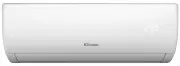
User Manual Dimplex DCES18


Summary
C O N T E N T S S A F E T Y P R E C A U T I O N S NAMES OF PARTS INDOOR UNIT DISPLAY OPERATING INSTRUCTIONS PROTECTION INSTALLATION MANUAL MAINTENANCE TROUBLESHOOTING EMERGENCY FUNCTION & AUTO-RESTART FUNCTION REMOTE CONTROLLER .......................................................................
1 During the installation of the indoor and outd-oor units the access to the working area should be forbidden to children.Unforeseeable accidents could happen. Make sure that the base of the outdoor unit isfirmly fixed. Check that air cannot enter the refrigerant sys- tem and check for refrigerant l...
2 SAFETY RULES AND RECOMMENDATIONS FOR THE USER Do not try to install the conditioner alone; always contact specialized technical personnel. Cleaning and maintenance must be carried out by specialised technical personnel. In any case disconnect the appliance from the mains elect-ricity supply before...
Dimplex Air Conditioners Manuals
-
 Dimplex DC09MINI
User Manual
Dimplex DC09MINI
User Manual
-
 Dimplex DC10RC
User Manual
Dimplex DC10RC
User Manual
-
 Dimplex DC10RCDH
User Manual
Dimplex DC10RCDH
User Manual
-
 Dimplex DC12PAC
User Manual
Dimplex DC12PAC
User Manual
-
 Dimplex DC12RCBW
User Manual
Dimplex DC12RCBW
User Manual
-
 Dimplex DC12RCDH
User Manual
Dimplex DC12RCDH
User Manual
-
 Dimplex DC15RCBW
User Manual
Dimplex DC15RCBW
User Manual
-
 Dimplex DC17
User Manual
Dimplex DC17
User Manual
-
 Dimplex DC18
User Manual
Dimplex DC18
User Manual
-
 Dimplex DCB05C
User Manual
Dimplex DCB05C
User Manual
-
 Dimplex DCB07
User Manual
Dimplex DCB07
User Manual
-
 Dimplex DCB07C
User Manual
Dimplex DCB07C
User Manual
-
 Dimplex DCB09
User Manual
Dimplex DCB09
User Manual
-
 Dimplex DCB09C
User Manual
Dimplex DCB09C
User Manual
-
 Dimplex DCB14
User Manual
Dimplex DCB14
User Manual
-
 Dimplex DCES09
User Manual
Dimplex DCES09
User Manual
-
 Dimplex DCES09B
User Manual
Dimplex DCES09B
User Manual
-
 Dimplex DCES09WIFI
User Manual
Dimplex DCES09WIFI
User Manual
-
 Dimplex DCES12
User Manual
Dimplex DCES12
User Manual
-
 Dimplex DCES18B
User Manual
Dimplex DCES18B
User Manual