Page 3 - IF YOU HAVE ANY QUESTIONS OR COMMENTS ABOUT THIS OR ANY D; Important Safety Instructions; ) POWER TOOL USE AND CARE
English 1 Defi nitions: Safety Guidelines The definitions below describe the level of severity for each signal word. Please read the manual and pay attention to these symbols. DANGER: Indicates an imminently hazardous situation which, if not avoided, will result in death or serious injury . WARNING: ...
Page 5 - English
English 3 • NEVER STAND ON TOOL. Serious injury could occur if the tool is tipped or if the cutting tool is unintentionally contacted. • ADDITIONAL INFORMATION regarding the safe and proper operation of power tools (i.e., a safety video) is available from the Power Tool Institute, 1300 Sumner Avenue...
Page 6 - DANGER–KEEP AWAY FROM BLADE.; WARNING: TO REDUCE THE RISK OF INJURY, USER MUST; Accessories; BLADE DESCRIPTIONS; General Purpose; Important Safety Instructions for All Battery Packs; DO NOT; The RBRCTM Seal; WALT. In some areas, it is illegal to place
English 4 For your convenience and safety, the following warning labels are on your miter saw. ON GUARD: DANGER–KEEP AWAY FROM BLADE. ON UPPER GUARD: PROPERLY SECURE BRACKET WITH BOTH SCREWS BEFORE USE. ON TABLE: (2 PLACES) WARNING: TO REDUCE THE RISK OF INJURY, USER MUST READ INSTRUCTION MANUAL BEF...
Page 8 - FAULTY BATTERY PACKS:; This charger will not charge a faulty battery pack. The charger; Wall Mounting; Do not freeze or immerse the charger in water or any other liquid.; Storage Recommendations; Charge Indicators; LEAVING THE BATTERY PACK IN THE CHARGER; Weak batteries will continue to function but should not be
English 6 FAULTY BATTERY PACKS: This charger will not charge a faulty battery pack. The charger will indicate faulty battery pack by refusing to light or by displaying problem pack or charger. NOTE: This could also mean a problem with a charger. PROBLEM POWER LINE (DCB101) Some chargers have a Probl...
Page 9 - INTENDED USE; Specifi cations; CAPACITY OF CUT; Special Cuts; IMPORTANT SAFETY INSTRUCTIONS
English 7 2. For long storage, it is recommended to store a fully charged battery pack in a cool dry place out of the charger for optimal results. NOTE: Battery packs should not be stored completely depleted of charge. The battery pack will need to be recharged before use. SAVE THESE INSTRUCTIONS FO...
Page 10 - Refer to
English 8 Changing or Installing a New Saw Blade (Fig. 4) Refer to Saw Blades under Optional Accessories for correct saw blade. WARNING: To reduce the risk of serious personal injury, turn tool off and remove the battery pack before making any adjustments or removing/installing attachments or access...
Page 11 - WARNING: To reduce the risk of serious personal injury, ALWAYS; FEATURES AND CONTROLS; Do not stare at operating lamp.; Charging
English 9 WARNING: • The guard bracket must be returned to its original full down position and the guard bracket screws tightened before activating the saw. Failure to do so may prevent the guard from closing or may allow the guard to contact the spinning saw blade resulting in damage to the saw and...
Page 12 - NEVER use the lock down pin for any cutting operation.; OPERATION; cut without power before making any cuts on the workpiece.
English 10 Bevel Lock Knob (Fig. 3, 6) The bevel lock allows you to bevel the saw 48° to the left. To adjust the bevel setting, turn the bevel lock knob (L) counterclockwise to loosen. To tighten, turn the bevel lock knob clockwise. CAUTION: Pinch hazard. Be sure to tighten bevel lock knob before ad...
Page 13 - An accidental
English 11 Dust Extraction (Fig. 3, 9) FIG. 9 N AQ WARNING: To reduce the risk of serious personal injury, turn tool off and remove the battery pack before making any adjustments or removing/installing attachments or accessories. An accidental start-up can cause injury. Your saw has a built-in dust ...
Page 14 - CLAMPING THE WORKPIECE; Rotate the clamp 180o toward the front of the; ADJUSTMENTS
English 12 FIG. 11A FIG. 11B FIG. 11C FIG. 11D CLAMPING THE WORKPIECE WARNING: To reduce the risk of serious personal injury, turn tool off and remove the battery pack before making any adjustments or removing/installing attachments or accessories. An accidental start-up can cause injury. WARNING: A...
Page 15 - Cutting Large Material; under; Support for Long Pieces; LESS THE BLADE IS
English 13 NOTE: Certain special cuts of large material will require that you manually raise the guard. Refer to Cutting Large Material under Special Cuts . The front section of the guard is louvered for visibility while cutting. Although the louvers dramatically reduce flying debris, they are openi...
Page 16 - Bevel Setting/Type of Cut
English 14 – EXAMPLES – NUMBER OF SIDES MITER OR BEVEL ANGLE 4 45° 5 36° 6 30° 7 25.7° 8 22.5° 9 20° 10 18° The chart assumes that all sides are of equal length. For a shape that is not shown in the chart, use the following formula: 180º divided by the number of sides equals the miter (if the materi...
Page 17 - PRETESTING WITH SCRAP MATERIAL IS EXTREMELY IMPORTANT!
English 15 BEVEL SETTING TYPE OF CUT 33.8° RIGHT SIDE, INSIDE CORNER: 1. Bottom of molding against fence 2. Miter table set left 31.62° 3. Save left end of cut 33.8° LEFT SIDE, OUTSIDE CORNER: 1. Bottom of molding against fence 2. Miter table set left 31.62° 3. Save right end of cut 33.8° RIGHT SIDE...
Page 18 - DUST DUCT CLEANING; Since accessories, other than those offered by D; CONFIRMATION OF OWNERSHIP:
English 16 MAINTENANCE WARNING: To reduce the risk of serious personal injury, turn tool off and remove the battery pack before making any adjustments or removing/installing attachments or accessories. An accidental start-up can cause injury. WARNING: To reduce the risk of serious personal injury, D...
Page 20 - TABLE 1: COMPOUND MITER CUT; SQUARE BOX; SET THIS BEVEL ANGLE ON SAW
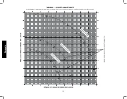
English 18 TABLE 1: COMPOUND MITER CUT (POSITION WOOD WITH BROAD FLAT SIDE ON THE TABLE AND THE NARROW EDGE AGAINST THE FENCE) SET THIS MITER ANGLE ON SA W ANGLE OF SIDE OF BOX (ANGLE A) SQUARE BOX 6-SIDED BOX SET THIS BEVEL ANGLE ON SAW 8-SIDED BOX
Page 21 - ) SÉCURITÉ DU LIEU DE TRAVAIL
19 Français Défi nitions : lignes directrices en matière de sécurité Les définitions ci-dessous décrivent le niveau de danger pour chaque mot-indicateur employé. Lire le mode d’emploi et porter une attention particulière à ces symboles. DANGER : indique une situation dangereuse imminente qui, si ell...
Page 22 - Français; S’assurer que les outils de coupe sont aiguisés et propres.; ) UTILISATION ET ENTRETIEN DU BLOC-PILES; Ne pas utiliser un bloc-piles ou un outil endommagé ou modifié.; Consignes de sécurité propres aux scies à onglet; Couper une pièce à la fois.
20 Français c) Débrancher la fiche de la source d’alimentation et/ou du bloc-piles de l’outil électrique avant de faire tout réglage ou changement d’accessoire ou avant de ranger l’outil. Ces mesures préventives réduisent les risques de démarrage accidentel de l’outil électrique. d) Ranger les outil...
Page 25 - DESCRIPTIONS DES LAMES; LIRE TOUTES LES CONSIGNES; NE PAS; Le sceau SRPRC
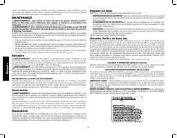
23 Français Accessoires AVERTISSEMENT : comme les accessoires autres que ceux offerts par D E WALT n’ont pas été testés avec ce produit, leur utilisation avec cet appareil pourrait comporter un danger. Pour réduire tout risque de dommages corporels, seuls des accessoires D E WALT recommandés doiven...
Page 26 - CONSERVER CES INSTRUCTIONS :; Calibres minimaux des rallonges; NE JAMAIS; Chargeurs
24 Français autorisé D E WALT ou chez votre détaillant afin qu’elles y soient recyclées. On peut en outre se renseigner auprès d’un centre de recyclage local pour connaître d’autres sites les acceptant.SRPRC MC est une marque déposée de la Société de recyclage des piles rechargeables au Canada . Dir...
Page 27 - FONCTION DE SUSPENSION DE CHARGE CONTRE LE CHAUD/FROID; s’attendre à un rendement moindre.; Installation murale
25 Français Fonctionnement du voyant DCB101 x DCB107, DCB112 Voyants de charge Ce chargeur a été conçu pour détecter les problèmes pouvant survenir. Un voyant rouge clignotant rapidement indique qu’il y a un problème. Dans cette éventualité, réinsérez le bloc-piles dans le chargeur. Si le problème p...
Page 28 - le chargeur, des chocs électriques pourraient en résulter.; Recommandations de stockage; USAGE PRÉVU; Caractéristiques techniques; CAPACITÉ DE COUPE; Coupes particulières
26 Français AVERTISSEMENT : risques de chocs électriques. Ne laisser aucun liquide pénétrer dans le chargeur, des chocs électriques pourraient en résulter. AVERTISSEMENT : risqu esde brûlure. Ne submerger le bloc-piles dans aucun liquide et le protéger de toute infiltration de liquide. Ne jamais ten...
Page 29 - Lames de scie
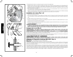
27 Français ATTENTION : pour éviter tout grippage et manque de précision, assurez-vous que la surface de montage n’est pas tordue et ne présente pas d’autre défaut. Si la scie bascule sur la surface, placez une pièce de matériau de faible épaisseur sous l’un des pieds de la scie, jusqu’à ce que cett...
Page 30 - jusqu’à enclencher le verrouillage.; CARACTÉRISTIQUES ET COMMANDES; Un démarrage accidentel peut provoquer des blessures.; Utilisation du dispositif d’éclairage DEL XPS; ne pas regarder droit dans la lampe allumée.; à l’aide de l’interrupteur
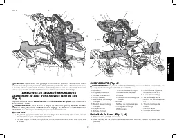
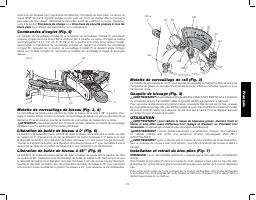
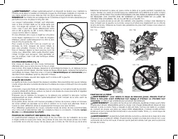
28 Français 3. Desserrez sans la retirer la vis arrière du support du carter (Y) de quatre tours. 4. Desserrez sans la retirer la vis avant du support de carter (X, fig. 4) jusqu’à ce que le support (Z) soit assez élevé pour donner accès à la vis de lame (AB). Le carter inférieur restera élevé à ca...
Page 31 - Procédure de charge; Directives de sécurité propres à tous les; de biseau avant d’ajuster les commandes prioritaires.; UTILISATION
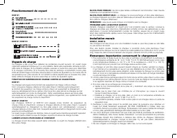
29 Français Votre scie est équipée d’un mécanisme de détection d’incidents du bloc-piles. La lampe de travail XPS MC se met à clignoter lorsque le bloc-piles est en fin de charge utile ou lorsque le bloc-piles est trop chaud. Rechargez le bloc-piles avant de continuer à couper. Reportez-vous à la se...
Page 32 - AVERTISSEMENT : pour réduire le risque; Un démarrage accidentel peut; POUR VIDER LE SAC À POUSSIÈRE; extracteur de poussière D; NE PAS DÉCOUPER DES MÉTAUX OU DE LA MAÇONNERIE AVEC; Réglages
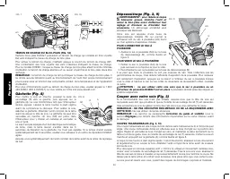
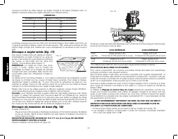
30 Français P FIG. 7 AO AP FIG. 7A TÉMOIN DE CHARGE DU BLOC-PILES (FIG. 7A) Certains blocs-piles D E WALT possèdent un témoin de charge qui consiste en trois voyants Del verts indiquant le niveau de charge du bloc-piles. Pour activer le témoin de charge, maintenir appuyé le bouton du témoin de charg...
Page 33 - Caractéristiques et commandes; QUALITÉ DE COUPE; sous; FIXATION DE LA PIÈCE
31 Français AVERTISSEMENT : utilisez systématiquement un dispositif de fixation pour maintenir le contrôle de la pièce à travailler et réduire les risques de dommages matériels et corporels, si vos mains doivent se trouver dans les 152 mm (6 po) de la lame pendant la découpe. REMARQUE : la molette ...
Page 34 - WALT; Tourner la bride de 180° vers l’avant de la scie à; RÉGLAGES
32 Français AVERTISSEMENT : utilisez systématiquement une bride de fixation pour maintenir le contrôle de la pièce à travailler et réduire les risques de dommages matériels et corporels, si vos mains doivent se trouver dans 152 mm (6 po) de la lame pendant la découpe. Si vous ne pouvez pas manuellem...
Page 35 - manuellement le carter. Se reporter à la section; Soutien des pièces longues
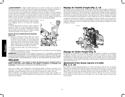
33 Français FIG. 14 Index de biseau (Fig. 6) Si l’index de biseau (AM) n’indique pas zéro, desserrez la vis maintenant en place l’index de biseau et déplacez-le comme nécessaire. Assurez-vous que le biseau à 0° est correct et que l’index de biseau est bien réglé avant d’ajuster toute autre vis d’ang...
Page 36 - Réglage du biseau/Type de coupe
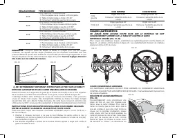
34 Français Lorsque le nombre de côtés change, les angles d’onglet et de biseau changent aussi. Le tableau ci-dessous indique les angles adéquats pour diverses formes. – EXEMPLES – NOMBRE DE CÔTÉS ANGLE D’ONGLET OU DE BISEAU 4 45° 5 36° 6 30° 7 25,7° 8 22,5° 9 20° 10 18° Le tableau suppose que tous ...
Page 37 - IL EST EXTRÊMEMENT IMPORTANT D’EFFECTUER UN TEST SUR UN REBUT !
35 Français RÉGLAGE BISEAU TYPE DE COUPE 33,8° CÔTÉ GAUCHE, COIN INTERNE : 1. Bord supérieur de la moulure contre le guide 2. Table d’onglet réglée à droite à 31,62° 3. Conservez l’extrémité gauche de la coupe 33,8° CÔTÉ DROIT, COIN INTERNE : 1. Bord inférieur de la moulure contre le guide 2. Table ...
Page 40 - TABLEAU 1 COUPE À ONGLET MIXTE; RÉGLEZ CET ANGLE D’ONGLET SUR LA SCIE; BOÎTE CARRÉE; RÉGLEZ CET ANGLE DE BISEAU SUR LA SCIE; BOÎTE À 8 F; ANGLE DE LA P
38 Français TABLEAU 1 COUPE À ONGLET MIXTE (POSITIONNEZ LE MORCEAU DE BOIS AVEC LE LARGE CÔTÉ PLAT CONTRE LA TABLE ET L’ARÊTE ÉTROITE CONTRE LE GUIDE.) RÉGLEZ CET ANGLE D’ONGLET SUR LA SCIE BOÎTE CARRÉE BOÎTE À 6 F ACES RÉGLEZ CET ANGLE DE BISEAU SUR LA SCIE BOÎTE À 8 F ACES ANGLE DE LA P AROI DE LA...
Page 41 - ) SEGURIDAD EN EL ÁREA DE TRABAJO
39 Español Defi niciones: Normas de seguridad Las siguientes definiciones describen el nivel de gravedad de cada palabra de señal. Lea el manual y preste atención a estos símbolos. PELIGRO: indica una situación de peligro inminente que, si no se evita, provocará la muerte o lesiones graves . ADVERTEN...
Page 42 - Español; instrucciones operen la herramienta.; ) USO Y MANTENIMIENTO DE LA HERRAMIENTA CON BATERÍAS; No utilice una batería o herramienta que esté dañada o modificada.
40 Español instrucciones operen la herramienta. Las herramientas eléctricas son peligrosas si son operadas por usuarios no capacitados. e) Realice el mantenimiento de las herramientas eléctricas. Revise que no haya piezas en movimiento mal alineadas o trabadas, piezas rotas o cualquier otra situació...
Page 44 - ADVERTENCIA: PARA REDUCIR EL RIESGO DE LESIONES,; Accesorios; WALT Industrial Tool Co., 701 East Joppa
42 Español o DC ....corriente directa o AC/DC ...corriente alterna o directa .................Construcción de Clase I no ...................velocidad sin carga (tierra) n......................velocidad nominal .................Construcción de Clase II) ....................terminal de conexión a tier...
Page 45 - DESCRIPCIONES DE LA HOJA; Propósito general; LEA TODAS LAS INSTRUCCIONES; El transporte de baterías puede causar incendios si sus; El sello RBRCTM; WALT y otros usuarios de baterías, han establecido
43 Español Accesorios opcionales Los siguientes accesorios, diseñados para su sierra, pueden resultarle útiles. En algunos casos, otros soportes para la pieza de trabajo, topes de longitud, abrazaderas, etc. que se obtengan localmente pueden ser más apropiados. Tenga cuidado al seleccionar y utiliza...
Page 46 - No exponga el cargador a la lluvia o a la nieve.; Cargadores
44 Español ADVERTENCIA: Peligro de descarga eléctrica. No permita que ningún líquido se introduzca en el cargador. Puede producir descargas eléctricas. ATENCIÓN: Peligro de quemaduras. Para reducir el riesgo de lesiones, sólo cargue unidades de batería recargables marca D E WALT. Otros tipos de bate...
Page 47 - RETARDO POR UNIDAD CALIENTE/FRÍA; Las baterías desgastadas seguirán; UNIDADES DE BATERÍA DEFECTUOSAS:; Este cargador no cargará una unidad de; LÍNEA DE ALIMENTACIÓN CON PROBLEMAS (DCB101); Peligro de descarga eléctrica. No permita que ningún líquido se
45 Español Indicadores de carga Este cargador ha sido diseñado para detectar ciertos problemas que pudieran surgir. Estos problemas se indican mediante una luz roja intermitente rápida. Si esto ocurre, vuelva a colocar la unidad de batería en el cargador. Si el problema persiste, pruebe con otra uni...
Page 48 - USO DEBIDO; Especifi caciones; CAPACIDAD DE CORTE; Riesgo de pellizco. Para; INSTRUCCIONES DE SEGURIDAD IMPORTANTES
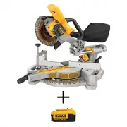
46 Español Desempaque de la sierra Compruebe el contenido de la caja de la sierra ingleteadora para asegurarse de que ha recibido todas las piezas.Además de este manual de instrucciones, la caja debe contener lo siguiente: 1 sierra ingleteadora DCS361 1 Hoja de sierra de 184 mm (7-1/4") de diáme...
Page 49 - piezas. Podría producir lesiones corporales o daños.
47 Español COMPONENTES (Fig. 3) ADVERTENCIA: Nunca modifique la herramienta eléctrica, ni tampoco ninguna de sus piezas. Podría producir lesiones corporales o daños. A. Interruptor de gatilloB. Mango de operaciónC. Orificios de montajeD. Protector inferiorE. Perilla de fijación de inglete F. Botón d...
Page 50 - CARACTERÍSTICAS Y CONTROLES; Un arranque accidental podría; Uso del Sistema de luz de trabajo LED XPS; No mire fijamente la lámpara en funcionamiento.
48 Español AA AC AB AD AE AF FIG. 4 Y AB Z X 3. Afloje, pero no saque el tornillo trasero del soporte del protector (Y) por cuatro revoluciones. 4. Afloje, pero no saque el tornillo frontal del soporte del protector (X, Fig. 4) hasta que el soporte (Z) pueda levantarse lo suficiente para acceder el ...
Page 51 - Procedimiento de carga; Instrucciones de seguridad importantes para todas las; de ajustar anulaciones.; FUNCIONAMIENTO; Un arranque accidental podría causar lesiones.
49 Español Para cortar una línea existente trazada a lápiz sobre un trozo de madera, encienda el sistema de luz de trabajo XPS TM utilizando el interruptor momentáneo (Q) (no con el gatillo principal), luego jale hacia abajo el mango de operación (B) para acercar la hoja de la sierra a la madera. La...
Page 52 - ADVERTENCIA: Para reducir el riesgo de; Un; PARA FIJAR LA BOLSA PARA POLVO; extractor de polvo D; NO CORTE METALES NI MAMPOSTERÍA CON ESTA SIERRA.; Ajustes
50 Español Cómo instalar y retirar la unidad de batería (Fig. 7) NOTA: Para mejores resultados, verifique que su unidad de batería esté completamente cargada. Para instalar la unidad de batería (P) en el mango de la herramienta, alinee la unidad de batería con los rieles en el interior del mango de ...
Page 53 - Use siempre una abrazadera de trabajo para mantener el control y; CALIDAD DEL CORTE; en; SUJECIÓN DE LA PIEZA DE TRABAJO
51 Español Al cortar piezas más grandes de 2 x 4 (51 x 102), use un movimiento hacia afuera, hacia abajo y hacia atrás con la perilla de bloqueo del riel (T) aflojada. Jale la sierra hacia afuera, hacia usted, baje el cabezal hacia la pieza de trabajo y empuje la sierra lentamente hacia atrás para c...
Page 54 - Gire la abrazadera 180° hacia el frente de la sierra; AJUSTES
52 Español ADVERTENCIA: El pie de la abrazadera debe permanecer sujetado con la abrazadera por encima de la base de la sierra siempre que se utilice la abrazadera. Siempre sujete la pieza de trabajo con la abrazadera a la base de la sierra (no a cualquier otra pieza del área de trabajo). Asegúrese d...
Page 55 - Corte de material grande; bajo la sección; Soporte de piezas largas; – EJEMPLOS –; NÚMERO DE LADOS
53 Español Indicador de bisel (Fig. 6) Si el indicador de bisel (AM) no indica cero, afloje el tornillo que lo sujeta en su sitio y muévalo según sea necesario. Asegúrese de que el bisel 0° sea correcto y el indicador de bisel esté fijado antes de ajustar cualquier otro tornillo de ángulo de bisel. ...
Page 56 - ESQUINA INTERIOR; Configuración de bisel/Tipo de corte; ¡ES SUMAMENTE IMPORTANTE REALIZAR PRUEBAS PRELIMINARES CON
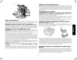
54 Español Corte de ingletes compuestos (Fig. 17) Los ingletes compuestos son cortes que se realizan FIG. 17 ANGLE “A” utilizando un ángulo de inglete y un ángulo de bisel en forma simultánea. Este tipo de corte se utiliza para hacer marcos o cajas con lados inclinados, como el que se muestra en la ...
Page 57 - Cortes especiales
55 Español NOTA: Al configurar los ángulos de bisel e inglete para todos los ingletes compuestos, recuerde que los ángulos presentados para las molduras de corona son muy precisos y difíciles de fijar exactamente. Puesto que pueden moverse ligeramente y muy pocas habitaciones tienen esquinas exactam...
Page 58 - LIMPIEZA DEL CONDUCTO DE EXTRACCIÓN DE POLVO; Debido a que no se han probado con este producto otros accesorios; Reparaciones; WALT, en un centro de mantenimiento; PARA REPARACIÓN Y SERVICIO DE SUS HERRAMIENTAS ELÉCTRICAS, FAVOR; Póliza de Garantía; EXCEPCIONES; Esta garantía no será válida en los siguientes casos:
56 Español • Regularmente quite el polvo y las astillas de madera de alrededor Y DEBAJO de la base y la mesa giratoria. Si bien hay ranuras para permitir que pasen los residuos, siempre se acumula algo de polvo. • Las escobillas están diseñadas para funcionar durante varios años. Si necesitan ser re...
Page 61 - TABLA 1: CORTE DE INGLETE COMPUESTO; CAJA CUADRADA; FIJE ESTE ÁNGULO DE BISEL EN LA SIERRA
59 Español TABLA 1: CORTE DE INGLETE COMPUESTO (UBIQUE LA MADERA CON EL LADO PLANO ANCHO SOBRE LA MESA Y EL BORDE ANGOSTO CONTRA EL REBORDE) FIJE ESTE ÁNGULO DE INGLETE EN LA SIERRA CAJA CUADRADA CAJA DE SEIS LADOS FIJE ESTE ÁNGULO DE BISEL EN LA SIERRA CAJA DE OCHO LADOS ÁNGULO DEL LADO DE LA CAJA ...


 Dewalt DCS361B
User Manual
Dewalt DCS361B
User Manual
 Dewalt DCS361BWCB246CK
User Manual
Dewalt DCS361BWCB246CK
User Manual
 Dewalt DCS361BWDCB240C
User Manual
Dewalt DCS361BWDCB240C
User Manual
 Dewalt DCS361M1
User Manual
Dewalt DCS361M1
User Manual
 Dewalt DCS361M1W205
User Manual
Dewalt DCS361M1W205
User Manual
 Dewalt DCS361M1W210
User Manual
Dewalt DCS361M1W210
User Manual
 Dewalt DCS361M1W600
User Manual
Dewalt DCS361M1W600
User Manual
 Dewalt DCS361M1WWX725B
User Manual
Dewalt DCS361M1WWX725B
User Manual
 Dewalt DCS781B
User Manual
Dewalt DCS781B
User Manual
 Dewalt DCS781BWDCB609
User Manual
Dewalt DCS781BWDCB609
User Manual
 Dewalt DCS781X1
User Manual
Dewalt DCS781X1
User Manual
 Dewalt DW716
User Manual
Dewalt DW716
User Manual
 Dewalt DWS713
User Manual
Dewalt DWS713
User Manual
 Dewalt DWS713W723
User Manual
Dewalt DWS713W723
User Manual
 Dewalt DWS713WDWX724
User Manual
Dewalt DWS713WDWX724
User Manual
 Dewalt DWS713WDWX725B
User Manual
Dewalt DWS713WDWX725B
User Manual
 Dewalt DWS715
User Manual
Dewalt DWS715
User Manual
 Dewalt DWS715W3128P5X2
User Manual
Dewalt DWS715W3128P5X2
User Manual
 Dewalt DWS715W723
User Manual
Dewalt DWS715W723
User Manual