Page 3 - GENERAL SAFETY RULES
1. For your own safety, read the instruction manual before operating the machine. Learning the machine’s application, limitations, and specific hazards will greatly minimize the possibility of accidents and injury. 2. Wear eye and hearing protection and always use safety glasses. Everyday eyeglasses...
Page 4 - ADDITIONAL SPECIFIC SAFETY RULES; SAVE THESE INSTRUCTIONS.
4 FAILURE TO FOLLOW THESE RULES MAY RESULT IN SERIOUS PERSONAL INJURY. ADDITIONAL SPECIFIC SAFETY RULES SAVE THESE INSTRUCTIONS. Refer to them often and use them to instruct others. 1. DO NOT OPERATE THIS MACHINE until it is completely assembled and installed according to the instructions. A machine...
Page 5 - have a qualified electrician check the receptacle.; EXTENSION CORDS; Use proper extension cords. Make; MINIMUM GAUGE EXTENSION CORD
5 GROUNDED OUTLET BOX CURRENT CARRYING PRONGS GROUNDING BLADE IS LONGEST OF THE 3 BLADES GROUNDING MEANS ADAPTER 1. All grounded, cord-connected machines: In the event of a malfunction or breakdown, grounding provides a path of least resistance for electric current to reduce the risk of electric sho...
Page 6 - FOREWORD; FUNCTIONAL DESCRIPTION; UNPACKING AND CLEANING; “REPLACING KNIVES”
6 FOREWORD The DELTA Model 22-590 is a 13" (330 mm) Portable Planer that has a cutting capacity of 13" (330mm) wide, 6" (152mm) thick and 1/8" (3.2 mm) deep. This machine has a powerful 15 amp 120 volt motor with a three-knife cutterhead. FUNCTIONAL DESCRIPTION CARTON CONTENTS NOTICE...
Page 7 - ASSEMBLY; HOW TO INSTALL THE DUST COLLECTION ATTACHMENT; Disconnect the machine from the power source.; HOW TO PREPARE FOR DUST MANAGEMENT; ASSEMBLY TOOLS REQUIRED
7 ASSEMBLY To reduce the risk of injury, turn unit off and disconnect it from power source before installing and removing accessories, before adjusting or when making repairs. An accidental start-up can cause injury. HOW TO INSTALL THE DUST COLLECTION ATTACHMENT C Fig. 4 Fig. 3 1. Remove the two scr...
Page 9 - OPERATION; OPERATIONAL CONTROLS AND ADJUSTMENTS; HOW TO START AND STOP THE PLANER; “ON”; “OFF”; Ensure that the lock prevents the switch from being turned on.; HOW TO USE THE CUTTERHEAD LOCK
9 OPERATION OPERATIONAL CONTROLS AND ADJUSTMENTS HOW TO START AND STOP THE PLANER To turn the planer “ON” , lift the paddle (A) Fig. 10. To turn the tool “OFF” , push the paddle down (Fig. 11). IMPORTANT: When the machine is not in use, the switch should be locked in the “OFF” position to prevent un...
Page 10 - “RECOMMENDED
RECOMMENDED DEPTH OF CUT N O T E : O n e re v o l u t i o n o f t h e c u t t e r h e a d a d j u s t i n g handle will move the cutterhead up or down 1/16" (1.6 mm). You can make a 1/8" (3.2 mm) depth-of-cut in soft woods up to 6" (152mm) wide and in hard woods up to 4" (102 mm) wid...
Page 11 - HOW TO USE THE ADJUSTABLE INDEXING RING; MACHINE USE; PROPER PLANING TECHNIQUES
1. Measure the thickness of a planed board. 2. Set the zero position of the ring (A) Fig. 18 to align with the arrow (B). 3. Rotate the handle to the desired depth of cut, as indicated on the ring. Each indicator on the ring is equivalent to 1/128" (.2 mm) for making minute cuts. 4. Plane the wo...
Page 12 - TROUBLESHOOTING; MAINTENANCE
SNIPE Snipe is a depression made when an unsupported end of your material drops toward the fl oor, causing the opposite end to lift up into the cutter head. TO AVOID SNIPE Feed the workpiece into the planer so it is level and remains fl at against the base at all times.Keep the workpiece level throu...
Page 13 - HOW TO ADJUST THE INFEED AND OUTFEED TABLES
13 8. Take this time also to clean the rollers (I) Fig. 22A.9. Your unit is equipped with double-edged knives. If the second edge of the knife has not been used, rotate the knife 180 degrees and replace on the cutterhead. Replace the knives if both sides have been used. 10. Attach the hold-down bar ...
Page 14 - SERVICE; To prevent the planer from start-; DELTA
14 SERVICE The depth adjustment scale (A) Fig. 23D on your planer is set at the factory. However, with extended use, the depth adjustment scale could show an incorrect measurement. To check the depth adjustment scale, plane a piece of scrap wood, noting the measurement on the depth adjustment scale....
Page 15 - FREE WARNING LABEL REPLACEMENT; AVERTISSMENT
15 FREE WARNING LABEL REPLACEMENT If your warning labels become illegible or are missing, call 1-800-223-7278 for a free replacement. AVERTISSMENT TO PROLONG TOOL LIFE, DURING KNIFE CHANGE CLEAN ANY PITCH OR WOOD BUILD UP FROM THE CUTTERHEAD. ALWAYS REMOVE THE KNIVES BEFORE CLEANING THE CUTTERHEAD. ...
Page 16 - ACCESSORIES; SERVICE AND REPAIRS; Five Year Limited New Product Warranty; WARRANTY
16 Since accessories other than those offered by DELTA have not been tested with this product, use of such accessories could be hazardous. For safest operation, only DELTA recommended accessories should be used with this product. A complete line of accessories is available from your DELTA Supplier, ...
Page 17 - LES INSTRUCTIONS IMPORTANTES DE SURETE; MESURES DE SÉCURITÉ – DÉFINITIONS
17 LES INSTRUCTIONS IMPORTANTES DE SURETE Lire toutes instructions d'avertissements et opération avant d'utiliser n'importe quel outil ou n'importe quel équipement. En utilisant les outils ou l'équipement, les précautions de sûreté fondamentales toujours devraient être suivies pour réduire le risque...
Page 18 - RÈGLES DE SÉCURITÉ GÉNÉRALES
18 1. Pour sa sécurité personnelle, lire la notice d’utilisation, avant de mettre la machine. En marche, et pour aussi apprendre l’application et les limites de la machine ainsi que les risques qui lui sont particuliers ainsi, les possibilités d’accident et de blessures seront beaucoup réduites. 2. ...
Page 19 - RÈGLES SPÉCIFIQUES ADDITIONNELLES DE SÛRETÉ; CONSERVER CES DIRECTIVES.
19 1. NE PAS FAIRE FONCTIONNER CET APPAREIL avant qu’il ne soit entièrement assemblé et installé conformément à ces directives. Un appareil mal assemblé peut provoquer des blessures graves. 2. DEMANDER CONSEIL à un superviseur, instructeur, ou toute autre personne qualifiée si l’on ne maîtrise pas p...
Page 20 - CORDON DE RALLONGE
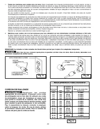
20 BOÎTE À PRISES MISE À LA TERRE BROCHES CONDUCTRICES DE COURANT LA BROCHE DE MISE À LA TERRE EST LA PLUS LONGUE DES TROIS OREILLE DE MISE À LA TERRE ADAPTATEUR 2. Machines avec cordon mis à la terre prévues pour une utilisation sur une alimentation nominale inférieure à 150 volts: Si cette machine...
Page 21 - DÉSEMBALLAGE ET NETTOYAGE
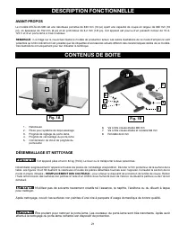
21 DESCRIPTION FONCTIONNELLE CONTENUS DE BOITE REMARQUE : La image sur la couverture illustre le modèle de production actuel. Les autres illustrations de ce mode d’emploi ne sont présentes qu’à titre indicatif et il est possible que les étiquettes et accessoires actuels diffèrent des caractéristique...
Page 22 - ASSEMBLAGE; INSTALLATION DE LA PIÈCE POUR SYSTÈME DE DÉPOUSSIÉRAGE; l’ÉTAPE 1; PRÉPARATION POUR LA GESTION DE LA POUSSIÈRE; OUTILS NÉCESSAIRES POUR L’ASSEMBLEE
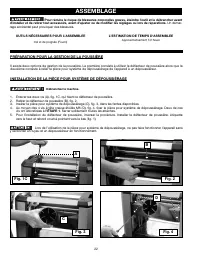
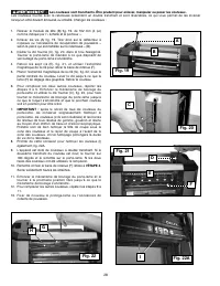
22 ASSEMBLAGE INSTALLATION DE LA PIÈCE POUR SYSTÈME DE DÉPOUSSIÉRAGE C Fig. 4 Fig. 3 1. Enlever les deux vis (A), fig. 1C, qui fixent le déflecteur de poussière.2. Retirer le déflecteur de poussière (B), fig. 2.3. Insérer la pièce pour système de dépoussiérage (C), fig. 3, dans les fentes disponible...
Page 23 - MÉTHODE DE FIXATION DE LA POIGNÉE DE VERROUILLAGE DU PORTE-LAME
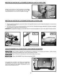
23 1. Fixer la poignée de réglage du porte-lame (A) fig. 6 à la tige (B) et s’assurer que le méplat de la tige est en prise avec le méplat de la poignée. 2. Au moyen d’une vis à tête creuse étoilée M6 x 20 mm et d’une rondelle de blocage, assembler la poignée de réglage du porte-lame à la tige avec ...
Page 24 - DÉMARRAGE ET ARRÊT DE MACHINE; FONCTIONNEMENT; L’OPERATION CONTROLE DE LE ET LES AJUSTEMENT; UTILISATION DU DISPOSITIF DE VERROUILLAGE DU PORTE-LAME
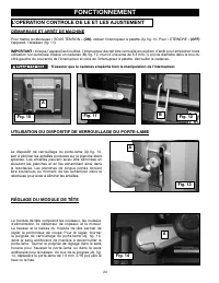
24 DÉMARRAGE ET ARRÊT DE MACHINE FONCTIONNEMENT L’OPERATION CONTROLE DE LE ET LES AJUSTEMENT S Pour mettre la raboteuse « SOUS TENSION » (ON) , relever l’interrupteur à palette (A), fig. 10. Pour « ETEINDRE » (OFF) l’appareil, l’abaisser (fig. 11). IMPORTANT : lorsque l’appareil est inutilisé, l’int...
Page 25 - PROFONDEUR DE COUPE RECOMMANDÉE; UTILISATION DU GUIDE D’ENLÈVEMENT DE MATIÈRE
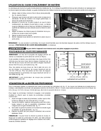
25 PROFONDEUR DE COUPE RECOMMANDÉE REMARQUE : un tour de la poignée de réglage permet de relever ou d’abaisser le porte-lame de 1,6 mm (1/16 po). Il est possible d’obtenir une profondeur de coupe de 3,2 mm (1/8 po) pour les bois mous dont la largeur maximum est de 152 mm (6 po) et pour les bois durs...
Page 26 - UTILISATION DE LA BAGUE D’INDEXAGE RÉGLABLE; TECHNIQUES APPROPRIÉES DE RABOTAGE; LARGEUR, HAUTEUR ET PROFONDEUR MINIMUMS ET MAXIMUMS; UTILISATION DE LA MACHINE
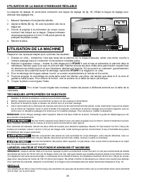
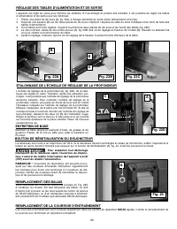
26 1. Mesurer l’épaisseur d’une planche rabotée. 2. Aligner la flèche (B), fig. 18, avec la position zéro de la bague (A). 3. Tourner la poignée à la profondeur de coupe voulue, comme il est indiqué sur la bague. Chaque indicateur de la bague équivaut à 0,2 mm (1/128 po) et permet de pratiquer de pe...
Page 27 - RABOTAGE D’UNE SURFACE TORDUE; RABOTAGE D’UNE SURFACE VOILÉE; DEPANNAGE; VÉRIFICATION, RÉGLAGE ET REMPLACEMENT DES COUTEAUX; gants de protection. Les lames de la raboteuse sont très acérées.
27 MÉTHODE POUR ÉVITER LES ENTAILLES Alimenter la pièce dans la raboteuse de sorte qu’elle est de niveau et qu’elle demeure bien à plat contre la base et ce, en tout temps. Pour maintenir la pièce de niveau tout au long du rabotage, l’attraper à la sortie de la raboteuse. Si la pièce à raboter est p...
Page 30 - GARDER LA MACHINE PROPRE; de l’utilisation d’air comprimé.; DÉMARRAGE IMPOSSIBLE
30 GARDER LA MACHINE PROPRE Dégager régulièrement toutes les conduites d’air avec de l’air comprimé sec. Toutes les pièces en plastique doivent être net-toyées à l’aide d’un chiffon doux humide. NE JAMAIS utiliser de solvants pour nettoyer les pièces en plastique. Les solvants peuvent dissoudre ou e...
Page 31 - REMPLACEMENT GRATUIT DE L'ÉTIQUETTE
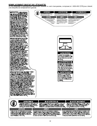
31 REMPLACEMENT GRATUIT DE L'ÉTIQUETTE Si vos étiquettes d’avertissement deviennent illisibles ou sont manquantes, composez le 1-800-223-7278 pour obtenir une étiquette de remplacement gratuite. AVERTISSMENT TO PROLONG TOOL LIFE, DURING KNIFE CHANGE CLEAN ANY PITCH OR WOOD BUILD UP FROM THE CUTTERHE...
Page 32 - ACCESSOIRIES; ENTRETIEN ET RÉPARATION; GARANTIE; Garantie limitée de cinq ans
32 Depuis des accessoires autre que ceux offertspar Porter-Cable•DELTA n’ont pas été testés avec ce produit, utilisation de tels accessoires a pu être dangereux. Pour l’exploitation sûre, seulement Porter-Cable•DELTA a recommandé des accessoires devrait être utilisé avec ce produit. Une ligne complè...
Page 33 - INSTRUCCIONES DE SEGURIDAD IMPORTANTES; PAUTAS DE SEGURIDAD/DEFINICIONES
33 Lea a todas advertencias y las instrucciones operadoras antes de utilizar cualquier instrumento o el equipo. Cuando se usa instrumentos o equipo, las precauciones básicas de la seguridad siempre se deben seguir para reducir el riesgo de la herida personal. La operación impropia, la conservación o...
Page 34 - NORMAS GENERALES DE SEGURIDAD
34 NORMAS GENERALES DE SEGURIDAD Si no se siguen estas normas, el resultado podría ser lesiones graves. 1. Para su propia seguridad, lea el manual de instrucciones antes de utilizar la máquina. Al aprender la aplicación, las limitaciones y los peligros específicos de la máquina, se minimizará enorme...
Page 35 - NORMAS ESPECÍFICAS ADICIONALES DE SEGURIDAD; GUARDE ESTAS INSTRUCCIONES.; CONEXIONES A LA FUENTE DE ALIMENTACIÓN
35 NORMAS ESPECÍFICAS ADICIONALES DE SEGURIDAD Si no se siguen estas normas, el resultado podría ser lesiones personales graves. GUARDE ESTAS INSTRUCCIONES. Refiérase a ellas con frecuencia y utilícelas para adiestrar a otros. 1. N O U T I L I C E E S TA M Á Q U I N A h a s t a q u e e s t é complet...
Page 36 - CORDÓN DE EXTENSIÓN DE CALIBRE MÍNIMO; CORDONES DE EXTENSIÓN
36 1. Todas las máquinas conectadas con cordón conectadas a tierra: En caso de mal funcionamiento o avería, la conexión a tierra proporciona una ruta de resistencia mínima para la corriente eléctrica, con el fin de reducir el riesgo de descargas eléctricas. Esta máquina está equipada con un cordón e...
Page 37 - DESCRIPCIÓN FUNCIONAL
37 PROLOGO El modelo DELTA 22-590 es una cepilladora portátil de 330 mm (13"), con una capacidad de corte de 330 mm (13") de ancho, 152 mm (6") de espesor y 3,2 mm (1/8") de profundidad. Esta máquina tiene un poderoso motor de 15 amperios y 120 voltios, con cabezal de corte de tres h...
Page 38 - HERRAMIENTAS DE ENSAMBLAJE REQUERIDAS; ENSAMBLAJE
38 Para reducir el riesgo de lesiones personales graves, apague la herramienta y desconéctela de la fuente de alimentación antes de instalar y retirar accesorios, ajustar o cambiar configuraciones o realizar reparaciones. Un arranque accidental podría causar lesiones. CÓMO INSTALAR EL ACCESORIO DE R...
Page 40 - ARRANCANDO Y DETENIENDO LA CEPILLADORA; CÓMO UTILIZAR EL BLOQUEO DEL CABEZAL DE CORTE; OPERACIÓN; CONTROLES Y AJUSTES OPERACIONALES
40 ARRANCANDO Y DETENIENDO LA CEPILLADORA Para encender la cepilladora, levante la paleta del interruptor (A) Fig. 10. Para apagar la herramienta, baje la paleta (Fig. 11). IMPORTANTE: Cuando no utilice la herramienta, bloquee el interruptor en la posición de “APAGADO”, para prevenir el uso no au- t...
Page 41 - PROFUNDIDADES DE CORTE RECOMENDADAS
41 NOTA: Una vuelta completa del mango de ajuste del cabezal de corte equivale a un movimiento del cabezal de corte de 1,6 mm (1/16") hacia arriba o hacia abajo. Puede realizar cortes con una profundidad de 3,2 mm (1/8") en maderas blandas de hasta 152 mm (6") de ancho y en maderas duras...
Page 42 - CÓMO UTILIZAR EL ANILLO INDICADOR AJUSTABLE; UTILIZACIÓN DE LA MÁQUINA; TÉCNICAS ADECUADAS DE CEPILLADO
42 1. Mida el espesor de una tabla cepillada. 2. Haga coincidir la posición cero del anillo (A) Fig. 18 con la flecha (B). 3. Gire el mango hasta alcanzar la profundidad de corte deseada, según se indica en el anillo. Cada indicador del anillo equivale a 0,2 mm (1/128") para realizar cortes minú...
Page 43 - LOCALIZACION DE FALLAS; MANTENIMIENTO
43 ANCHO/ALTURA/PROFUNDIDAD MÍNIMOS/MÁXIMOS NOTA: Siempre cepille siguiendo la dirección de la veta. Sostenga la pieza de trabajo en forma correcta en todo momento. No se recomienda cepillar material con menos de 19 mm (3/4") de ancho. Si debe cepillar materiales angostos, siempre que sea posibl...
Page 46 - SERVICIO
46 PIEZAS DE REPUESTO Utilice sólo piezas de repuesto idénticas. Para obtener una lista de piezas o para solicitar piezas, visite nuestro sitio web en www.deltaportercableservicenet.com . También puede solicitar piezas en nuestro centro más cercano, o llamando a nuestro Centro de atención al cliente...
Page 47 - REEMPLAZO GRATUITO DE LAS ETIQUETAS DE ADVERTENCIA
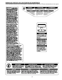
47 REEMPLAZO GRATUITO DE LAS ETIQUETAS DE ADVERTENCIA Si las etiquetas de advertencia se tornan eligibles o se pierden, llame al 1-800-223-7278 para reemplazarlas sin costo alguno. AVERTISSMENT TO PROLONG TOOL LIFE, DURING KNIFE CHANGE CLEAN ANY PITCH OR WOOD BUILD UP FROM THE CUTTERHEAD. ALWAYS REM...
Page 48 - ACCESORIOS; MANTENIMIENTO Y REPARACIONES; IDENTIFICACIÓN DELPRODUCTO:; PÓLIZA DE GARANTÍA
48 Puesto que los accesorios con excepción de ésos ofrecidos por DELTA no se han probado con este producto, el uso de tales accesorios podría ser peligroso. Para la operación más segura, solamente el DELTA recomendó los accesorios se debe utilizar con este producto. Una línea completa de accesorios ...
Page 49 - GARANTIA; Garantía limitada de cinco años para productos nuevos
49 GARANTIA Para registrar la herramienta para obtener el mantenimiento cubierto por la garantía de la herramienta, visite nuestro sitio Web en www.deltaportercable.com. Garantía limitada de cinco años para productos nuevos DELTA reparará o reemplazará, a expensas y opción propias, cualquier máquina...