Dell J730N- Manuals
Dell J730N– User Manual, Manual in PDF format online.
Manuals:
User Manual Dell J730N
Manual Dell J730N
Summary
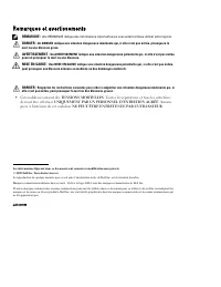
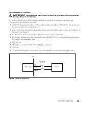
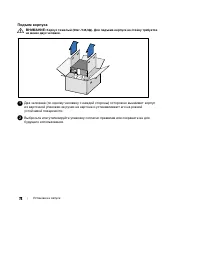
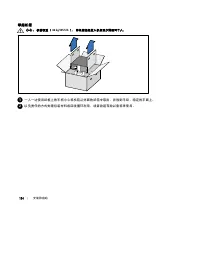
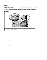
Notes and Warnings NOTE: A NOTE indicates important information that helps you make better use of your software. DANGER: A DANGER indicates an imminently hazardous situation which, if not avoided, will result in death or serious injury. WARNING: A WARNING indicates a potentially hazardous situation ...
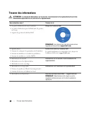
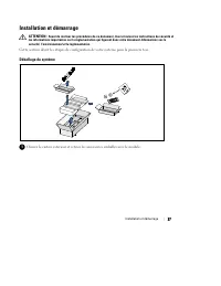
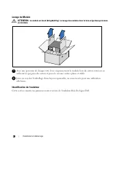
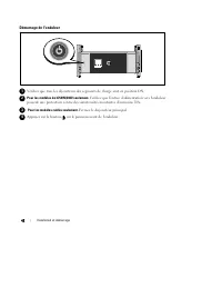
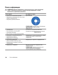
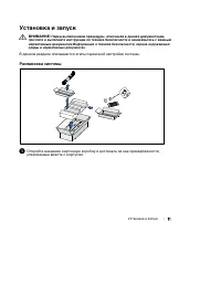
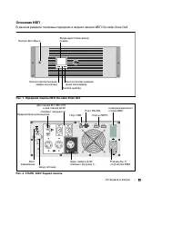
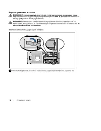
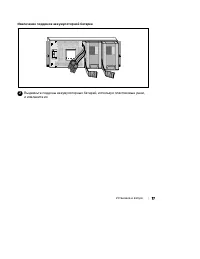
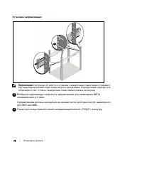
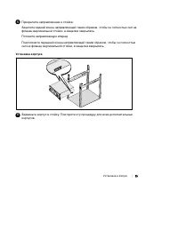
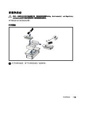
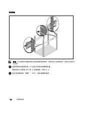
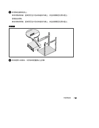
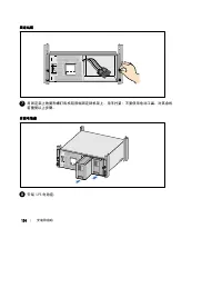
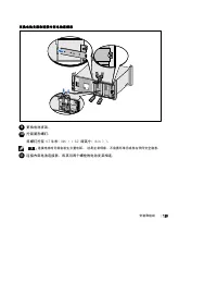
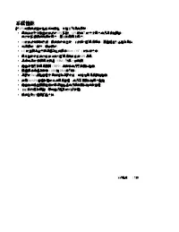
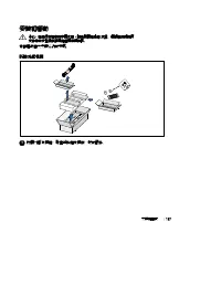
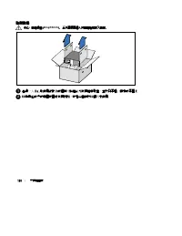
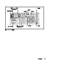
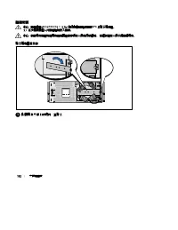
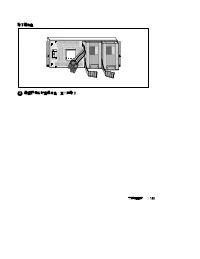
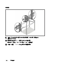
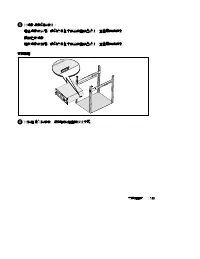
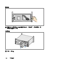
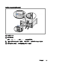
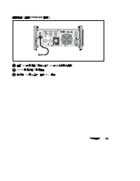
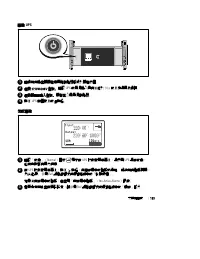
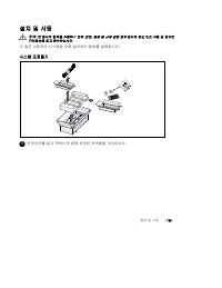
3 Table of Contents | Table of Contents 1 Introduction Finding Information 8 . . . . . . . . . . . . . . . . . . . . . . . . . . . . . . . . . . . . . . . . . . . . . . . 2 Safety Warnings 3 Installation Inspecting the Equipment 12 . . . . . . . . . . . . . . . . . . . . . . . . . . . . . . . . . . ...
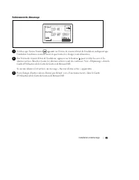
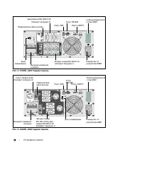
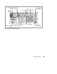
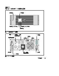
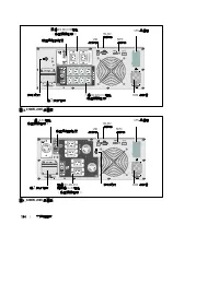
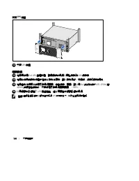
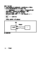
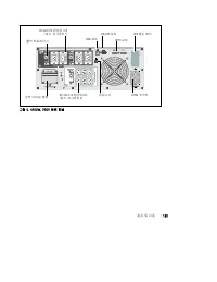
4 | Table of Contents Display Functions 34 . . . . . . . . . . . . . . . . . . . . . . . . . . . . . . . . . . . . . . . . . . . . . . . . Startup Screen 34 . . . . . . . . . . . . . . . . . . . . . . . . . . . . . . . . . . . . . . . . . . . . . . . Screen Locked 35 . . . . . . . . . . . . . . . . ...
5 Table of Contents | 6 UPS Maintenance UPS and Battery Care 58 . . . . . . . . . . . . . . . . . . . . . . . . . . . . . . . . . . . . . . . . . . . . . Transporting the UPS 58 . . . . . . . . . . . . . . . . . . . . . . . . . . . . . . . . . . . . . . . . . . . . . Storing the UPS and Batteries 60...
6 | Introduction Introduction The Dell t Online Rack uninterruptible power system (UPS) protects your sensitive electronic equipment from basic power problems such as power failures, power sags, power surges, brownouts, andline noise. Power outages can occur when you least expect them and power qual...
7 Introduction | Providing outstanding performance and reliability, the UPS's unique benefits include: S Online UPS design with pure sine wave output. The UPS filters and regulates incoming AC powerand provides consistent power to your equipment without draining the battery. S True online double-con...
8 | Introduction Finding Information CAUTION: The Safety, Environmental, and Regulatory Information document provides important safety and regulatory information. What are You Looking For? Find It Here S The user's guide for my UPS S The user's guide for the Dell Network ManagementCard S Dell UPS Ma...
9 Safety Warnings | Safety Warnings CAUTION: Before performing the procedures in this document, read and follow the safety instructions and important regulatory information in your Safety, Environmental, and Regulatory Information document. IMPORTANT SAFETY INSTRUCTIONSSAVE THESE INSTRUCTIONS This m...
11 Safety Warnings | WARNING: Additional instructions for Rack-Mounted Systems S Your rack kit has been approved only for the rack cabinet provided. It is your responsibility toensure that installation of the equipment into any other rack complies with all applicablestandards. Dell disclaims all lia...
12 | Installation Installation This chapter explains: S Equipment inspection S Unpacking the cabinet S UPS rear panels S UPS setup and installation, including the External Battery Module (EBM) S Remote Emergency Power-off (REPO) installation S Initial startup Inspecting the Equipment If any equipmen...
13 Installation | Unpacking the Cabinet CAUTION: Unpacking the cabinet in a low-temperature environment may cause condensation to occur in and on the cabinet. Do not install the cabinet until the inside and outside of the cabinet are absolutely dry (hazardof electric shock). CAUTION: The cabinet is ...
15 Installation | Identifying the UPS Rear Panels This section shows the rear panels of the Dell Online Rack models. UPSCommunication Bay 2m, L6-30P Power Cord USB Port One L6-30 Receptacle(Load Segment 1) REPO Ports RS-232 Port Ground Screw Two IEC 320-C19 and Two L6-20 Receptacles (Load Segment 2)...
17 Installation | UPSCommunication Bay Input Terminal Block USB Port Six IEC 320-C13 Receptacles(Load Segment 2) REPO Ports RS-232 Port Ground Screw Four IEC 320-C19 Receptacles (Load Segment 1) EBM Connector Output Circuit Breaker Figure 7. 4200W, 230V Rear Panel Identifying the UPS Front Panel On/...
18 | Installation Rackmount Setup CAUTION: The cabinet is heavy (see page 62): 1) Dell strongly recommends to remove the battery tray from the UPS before lifting. 2) Lifting the cabinets into the rack requires a minimum of two people. CAUTION: Removing the batteries should be performed or supervised...
19 Installation | Pull the battery trays out using the plastic tabs and remove the battery trays (see Figure 10). Figure 10. Removing the Battery Trays 2 If installing additional UPSs, repeat Step 1 for each cabinet. NOTE: The instructions are the same for square-hole racks and unthreaded, round-hol...
20 | Installation 5 Attach the rails to the rack: Engage the back end of the rail until it fully seats on the vertical rack flange and the hook latchlocks in place (see Figure 11). Pull the rail toward the front. Push the front end of the rail until it fully seats on the vertical rack flange and the...
23 Installation | 9 Replace the battery retaining bracket (see Figure 15). 10 Tighten the thumbscrew. Torque the screw to 0.7 Nm (6.2 lb in). NOTE: A small amount of arcing may occur when connecting the batteries. This is normal and does not damage the unit or present any safety concern. 11 Connect ...
24 | Installation 12 Install the UPS front cover (see Figure 16). Figure 16. Installing the UPS Front Cover Installing the EBM NOTE: A small amount of arcing may occur when connecting an EBM to the UPS. This is normal and will not harm personnel. Insert the EBM cable into the UPS battery connector q...
25 Installation | Installing the UPS To install the UPS: 1 If you plan to use Dell UPS Management Software, connect your computer to the USB port usingthe supplied cable. For more information about communication options, see page 54. 2 If your rack has conductors for grounding or bonding of unground...
26 | Installation CAUTION: To ensure the UPS stops supplying power to the load during any mode of operation, the input power must be disconnected from the UPS when the emergency power-off function is activated. NOTE: For Europe, the emergency switch requirements are detailed in Harmonized document H...
27 Installation | NOTE: A separate contact must simultaneously cause UPS input AC power to be removed. 5 Connect the switch or circuit to the REPO connector on the UPS rear panel using insulated0.75 mm 2 –0.5 mm 2 (18–20 AWG) wire. Optional. If you are daisy-chaining the REPO function with another U...
28 | Installation AC Mains Wall 2-pole Breaker UPS Line Neutral Figure 19. Circuit Breaker Diagram To hardwire the UPS input: 1 Switch off utility power at the distribution point where the UPS will be connected. Be absolutelysure there is no power. 2 Remove the terminal block cover (four screws) and...
29 Installation | 5 Insert the conduit through the wiring access entry and attach the conduit fitting to the panel.Strip 0.5 ” (1.5 cm) of insulation from the end of each incoming wire. 6 Connect the input and ground wires to the terminal block according to Figure 21 and Table 1. Figure 21. UPS Inpu...
30 | Installation 4 For 3750W/208V models only. Verify that the power input to the UPS has a minimum of 30A upstream overcurrent protection. Plug the UPS power cord into a power outlet. The UPS front panel display illuminates. The Dell startup screen changes to the UPS statussummary screen. The UPS ...
31 Operation | Operation This chapter contains information on how to use the UPS, including: S UPS startup and shutdown S Control panel and display functions S Retrieving the Event Log S Transferring the UPS between modes S Setting power strategy S Behavior on overload S Configuring load segments, b...
32 | Operation 4 On the UPS status summary screen, press the button to check for active alarms or notices.Resolve any active alarms before continuing. See “Troubleshooting” on page 66. If there are no active alarms, a “No Active Alarms” message appears. 5 Verify that the Normal mode icon appears on ...
33 Operation | Control Panel Functions The UPS has a three-button graphical LCD with dual color backlight. Standard backlight is used tolight up the display with white text and a blue background. When the UPS has a critical alarm, thebacklight changes the text to dark amber and the background to amb...
34 | Operation To select an option: 1 When scrolling through the settings, the present setting displays for each selection. 2 Press the button to select the option. The current setting for the option flashes when selected. 3 Use the or buttons to toggle the available options. 4 Set the new option by...
35 Operation | Screen Locked To lock a screen, press the button. The current view stays locked and does not automatically return to the default screen after time-out. When the screen is locked, the image of a key appears on the UPSstatus summary screen just to the left of the status icon. See Figure...
38 | Operation Table 4 describes the available battery status screens. Only one battery status is available at a time. Table 4. Battery Status Screens Battery Status Screen Description Battery charging Batteries are charged in constant current mode. Battery floating Batteries are charged in constant...
39 Operation | Measurements The measurements screens provide useful measurement information on: S Output watts VA, current, power factor, voltage, and frequency S Input voltage and frequency S Battery voltage and percentage charged S Instantaneous Headroom Watts remaining S Peak Headroom Watts (the ...
40 | Operation Control Screens Table 5 describes the available control screens. Table 5. Control Screens Control Screens Description Go to Bypass Transfers the UPS system to internal Bypass mode. When the Go to Bypass command is issued, the screen immediately shows themessage for five seconds: Manua...
41 Operation | Identification The identification screens display the following UPS information: S Type and model S Part number S Serial number S UPS firmware S Network Management Card (NMC) firmware NOTE: The NMC firmware screen displays only if the NMC is installed. See “Dell Network Management Car...
42 | Operation Settings Only available options are displayed. User settings are not protected by default. You can enable the password through the User Passwordsetting. Table 6 displays the options that can be changed by the user. Table 6. Settings Description Available Settings Default Setting Chang...
46 | Operation Table 6. Settings (continued) Description Default Setting Available Settings Reset Peak Headroom Watts [No] [Yes] If No, no action. If Yes, the Peak Headroom Watts value is clearedand the date and time stamp for this statistic is setto the current date and time. No Clear Event Log The...
47 Operation | Transferring from Bypass to Normal Mode To transfer from Bypass to Normal mode: 1 Press the button for one second to go to the main menu selection and scroll down to the Control menu using the button. 2 Press the button to enter the Control menu. 3 Select Go to Normal. The text on the...
48 | Operation Retrieving the Event Log To retrieve the Event Log through the display: 1 Press the button for one second to go to the main menu selection and scroll down to the Event Log menu using the button. 2 Press the button to enter the Event Log list. 3 Scroll through the listed events, notice...
49 Operation | Configuring Load Segments Load segments are sets of receptacles that can be controlled by the Dell UPS Management Software,the Dell Network Management Card, or through the LCD display, providing an orderly shutdown andstartup of your equipment. For example, during a power outage, you ...
50 | Operation Configuring Automatic Start Delay You can configure the load segment to turn on automatically after the utility power returns, if it wasshut down by: S The button S An external command with auto-restart option S Battery under voltage state S Automatic on battery shutdown command You c...
51 Operation | Configuring Automatic on Battery Shutdown If set to Off (default), the load segment turns off only when commanded manually by the button, an external command, or through the display (Control > Load Segments). If set to zero seconds (0s), the load segment turns off automatically whe...
52 | Operation Configuring Battery Settings Configure the UPS settings for an installed EBM, including whether to run automatic battery tests andautomatic restart configuration. Configuring the UPS for an EBM If the UPS is not configured for the EBM, the UPS reports less battery time remaining on th...
53 Operation | Running Automatic Battery Tests The automatic discharge test, enabled by default, runs during the transition from Float to Rest mode.After the test completes, the charge cycle restarts to completely charge the batteries and then continuesto Rest mode normally. The automatic test runs ...
54 | Additional UPS Features Additional UPS Features This chapter describes: S Communication ports (RS-232 and USB) S Dell Network Management Card S Dell UPS Management Software RS-232 and USB Communication Ports To establish communication between the UPS and a computer, connect your computer to one...
56 | Additional UPS Features Dell Network Management Card (Optional) The Dell Online Rack UPS has one available communication bay, which supports the optional DellNetwork Management Card. See Figure 25 for the location of the communication bay. It is not necessary to shut down the UPS before install...
57 Additional UPS Features | Dell UPS Management Software Each Dell Online Rack UPS ships with Dell UPS Management Software. Dell UPS Management Software provides up-to-date graphics of UPS power and system data and powerflow. It also gives you a complete record of critical power events, and it noti...
58 | UPS Maintenance UPS Maintenance This chapter explains how to: S Care for the UPS and batteries S Transport the UPS S Store the UPS and batteries S Test the batteries S Update the UPS firmware UPS and Battery Care For the best preventive maintenance, keep the area around the UPS clean and dust‐f...
60 | UPS Maintenance 5 Replace the UPS front cover (see Figure 28). Figure 28. Replacing the UPS Front Cover Storing the UPS and Batteries If you store the UPS for a long period, recharge the battery every 6 months by plugging the UPS into apower outlet. The batteries charge to 90% capacity in appro...
61 UPS Maintenance | Testing Batteries For a battery test to run: S The batteries must be fully charged. S The UPS must be in Normal mode or High Efficiency mode with no active alarms. S The load must be higher than 10%. To test batteries: 1 Plug the UPS into a power outlet for at least 48 hours to ...
62 | Specifications Specifications This chapter provides the following specifications: S Model list S Dimensions and weights S Electrical input and output S Environmental and safety S Battery S UPS block diagram Table 9. UPS Model List 208V Model 230V Models UPS Models 3750R OL (K804N), 3750W 4700R ...
66 | Troubleshooting Troubleshooting The Dell Online Rack UPS is designed for durable, automatic operation and issues alarms to alert youwhenever potential operating problems occur. Usually the alarms shown by the control panel do notmean that the output power is affected. Instead, they are preventi...
67 Troubleshooting | Event Log Menu From the Event Log menu, you can access the last 50 events, which includes events, notices, andalarms, arranged from newest to oldest. Events are silent conditions that are recorded in the Event Log as status information, such as “Clock SetDone.” Events do not req...
71 Troubleshooting | Table 15. Typical Alarms and Conditions (continued) Alarm or Condition Action Possible Cause DC Link Over Voltage (Alarm 28) Continuous Alarm The link or rail voltage hasexceeded its upper thresholdlimit. The UPS transfers to Bypass mode ifsupporting the load. DC Link Under Volt...
Dell Manuals
-
Dell 04YJJ6A00
User Manual
-
Dell 04YJJ6A00
Manual
-
Dell 10 Pro
User Manual
-
Dell 10
Manual
-
Dell 1000
User Manual
-
Dell 1000
Manual
-
Dell 1014
User Manual
-
Dell 1000W
User Manual
-
Dell 1000W
Manual
-
Dell 0JH552A01
User Manual
-
Dell 10g
User Manual
-
Dell 1100
User Manual
-
Dell 1100
Manual
-
Dell 11
User Manual
-
Dell 11
Manual
-
Dell 11 Pro
User Manual
-
Dell 110T
User Manual
-
Dell 110T DLT1 Drive
User Manual
-
Dell 1100 Laser Mono Printer
User Manual
-
Dell 1100MP
User Manual