Page 3 - Contents
Contents 1 About Your System......................................................................................................................7 Front-Panel Features And Indicators .......................................................................................................................
Page 7 - About Your System; Front-Panel Features And Indicators
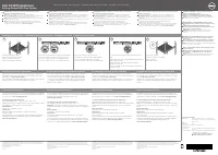
1 About Your System Front-Panel Features And Indicators Figure 1. Front-Panel Features and Indicators Item Indicator, Button, or Connector Icon Description 1 Diagnostic indicators The diagnostic indicators light up to display error status. 2 System health indicator The system health indicator blinks...
Page 8 - Diagnostic Indicators
Item Indicator, Button, or Connector Icon Description If the system stops responding during POST, press and hold the system ID button for more than five seconds to enter BIOS progress mode.To reset the iDRAC (if not disabled in F2 iDRAC setup) press and hold the button for more than 15 seconds. 6 Mi...
Page 9 - Hard-Drive Indicator Patterns
Memory indicator Condition Corrective Action The indicator blinks amber if a memory error occurs. See the system event log or system messages for the location of the failed memory. Reinstall the memory device. If the problem persists, see Getting Help. Hard-Drive Indicator Patterns Figure 2. Hard-Dr...
Page 10 - Back-Panel Features And Indicators
Drive-Status Indicator Pattern (RAID Only) Condition Blinks green three seconds, amber three seconds, and off six seconds Rebuild aborted Back-Panel Features And Indicators Figure 3. Back-Panel Features and Indicators Item Indicator, Button, or Connector Icon Description 1 System identification butt...
Page 11 - NIC Indicator Codes; Power Indicator Codes
Item Indicator, Button, or Connector Icon Description 9 Ethernet connectors (4) Four integrated 10/100/1000 Mbps NIC connectorsorTwo integrated 10/100/1000 Mbps NIC connectors and Two integrated 100 Mbps/1 Gbps/10 Gbps SFP+ connectors 10 PCIe expansion card slot (riser 3) Allows you to connect a PCI...
Page 12 - Other Information You May Need
Figure 5. AC Power Supply Status Indicator 1. AC power supply status indicator/handle Power Indicator Pattern Condition Not lit Power is not connected. Green The handle lights green indicating that a valid power source is connected to the power supply and that the power supply is operational. Flashi...
Page 15 - Using The System Setup And Boot Manager; Entering System Setup
2 Using The System Setup And Boot Manager CAUTION: It is recommended that you make BIOS changes only during support calls with certified Dell technicians. NOTE: Solution validation was performed using the factory shipped hardware configuration. System Setup enables you to manage your system hardware...
Page 16 - System Setup Options; System Setup Main Screen
If your operating system begins to load before you press <F2>, allow the system to finish booting, and then restart your system and try again. Responding To Error Messages If an error message is displayed while the system is booting, make a note of the message. For more information, see System...
Page 18 - Processor Settings Screen
Menu Item Description Video Memory Displays the amount of video memory. System Memory Testing Specifies whether system memory tests are run during system boot. Options are Enabled and Disabled. By default, the System Memory Testing option is set to Disabled. Memory Operating Mode Specifies the memor...
Page 20 - Integrated Devices Screen
Menu Item Description NOTE: UEFI is not supported on this system. Boot Sequence Retry Allows you to enable or disable the boot sequence retry feature. If this field is enabled and the system fails to boot, the system reattempts the boot sequence after 30 seconds. By default, the Boot Sequence Retry ...
Page 22 - System Security Screen
Menu Item Description CPU Power Management Allows you to set the CPU power management. By default, the CPU Power Management option is set to System DBPM (DAPC). DBPM is Demand-Based Power Management. Memory Frequency Allows you to set the memory frequency. By default, the Memory Frequency option is ...
Page 23 - Miscellaneous Settings
Menu Item DescriptionIntel TXT fields if the TPM Status field is set to either On with Pre-boot Measurements or On without Pre-boot Measurements. TPM Activation Allows you to change the operational state of the TPM. By default, the TPM Activation option is set to No Change. TPM Status Displays the T...
Page 24 - System And Setup Password Features; Assigning A System And/Or Setup Password
Menu Item Description F1/F2 Prompt on Error Allows you to enable or disable the F1/F2 prompt on error. By default, F1/F2 Prompt on Error is set to Enabled. In-System Characterization This field enables or disables In-System Characterization. By default, In-System Characterization is set to Enabled. ...
Page 25 - Deleting Or Changing An Existing System And/Or Setup Password; Using Your System Password To Secure Your System
6. Re-enter the system password that you entered earlier and click OK. 7. Select Setup Password, enter your system password and press <Enter> or <Tab>.A message prompts you to re-enter the setup password. 8. Re-enter the setup password that you entered earlier and click OK. 9. Press <...
Page 26 - Operating With A Setup Password Enabled; Embedded System Management; Entering The iDRAC Settings Utility
Operating With A Setup Password Enabled If Setup Password is Enabled, enter the correct setup password before modifying most of the System Setup options.If you do not enter the correct password in three attempts, the system displays the message Invalid Password! Number of unsuccessful password attem...
Page 27 - Installing System Components; Recommended Tools; Removing The Front Bezel
3 Installing System Components NOTE: Solution validation was performed using the factory shipped hardware configuration. CAUTION: Many repairs may only be done by a certified service technician. You should only perform troubleshooting and simple repairs as authorized in your product documentation, o...
Page 28 - Installing The Front Bezel; Opening And Closing The System; Opening The System
2. keylock3. front bezel4. locking hook Installing The Front Bezel 1. Hook the right end of the bezel onto the chassis. 2. Fit the free end of the bezel onto the system. 3. Secure the bezel with the keylock. Opening And Closing The System WARNING: Whenever you need to lift the system, get others to ...
Page 29 - Closing The System; Inside The System
Figure 7. Opening and Closing the System 1. system cover2. latch3. latch release lock Closing The System 1. Lift the latch on the cover. 2. Place the cover onto the chassis and offset the cover slightly back so that it clears the chassis hooks and lays flush on the chassis. 3. Push down the latch to...
Page 30 - Cooling Shroud; Removing The Cooling Shroud
Figure 8. Inside the System 1. control panel 2. cable securing clip3. cooling fans (7)4. cable securing bracket5. cooling shroud6. power supplies (2)7. chassis intrusion switch8. riser card 39. network daughter card 10. riser card 111. storage controller card12. network daughter card cooling shroud1...
Page 31 - Installing The Cooling Shroud; System Memory
Figure 9. Removing and Installing the Cooling Shroud 1. cooling shroud Installing The Cooling Shroud CAUTION: Many repairs may only be done by a certified service technician. You should only perform troubleshooting and simple repairs as authorized in your product documentation, or as directed by the...
Page 33 - Mode-Specific Guidelines; Memory Configuration; Removing Memory Modules
channel 2: slots B3, B7, and B11 channel 3: slots B4, B8, and B12 Mode-Specific Guidelines Four memory channels are allocated to each processor. The allowable configurations depend on the memory mode selected. NOTE: x4 and x8 DRAM based DIMMs can be mixed providing support for RAS features. However,...
Page 35 - Installing Memory Modules
7. Install the cooling shroud. 8. Close the system. 9. Reconnect the system to its electrical outlet and turn the system on, including any attached peripherals. Installing Memory Modules WARNING: The memory modules are hot to the touch for some time after the system has been powered down. Allow time...
Page 36 - Hard Drives
Figure 13. Installing The Memory Module 1. memory module2. memory-module ejectors3. memory-module socket alignment key4. memory-module alignment key NOTE: When the memory module is properly seated in the socket, the levers on the memory-module socket align with the levers on the other identical sock...
Page 37 - Removing A Hot-Swap Hard Drive; Installing A Hot-Swap Hard Drive
Removing A Hot-Swap Hard Drive CAUTION: To prevent data loss, ensure that your operating system supports hot-swap drive installation. See the documentation supplied with your operating system. 1. From the management software, prepare the hard drive for removal. Wait until the indicators on the hard-...
Page 38 - Removing A Hard Drive From A Hard-Drive Carrier
CAUTION: When a replacement hot-swappable hard drive is installed and the system is powered on, the hard drive automatically begins to rebuild. Make absolutely sure that the replacement hard drive is blank or contains data that you wish to have over-written. Any data on the replacement hard drive is...
Page 39 - Installing A Hard Drive Into A Hard-Drive Carrier; Cooling Fans; Removing A Cooling Fan
Installing A Hard Drive Into A Hard-Drive Carrier CAUTION: Many repairs may only be done by a certified service technician. You should only perform troubleshooting and simple repairs as authorized in your product documentation, or as directed by the online or telephone service and support team. Dama...
Page 40 - Installing A Cooling Fan; Expansion Cards And Expansion-Card Risers; Expansion Card Installation Guidelines
Figure 16. Removing and Installing a Cooling Fan 1. cooling fan assembly2. cooling fans (7)3. cooling fan connectors (7) Installing A Cooling Fan CAUTION: Many repairs may only be done by a certified service technician. You should only perform troubleshooting and simple repairs as authorized in your...
Page 41 - Removing An Expansion Card
Riser PCIe Slot Processor Connection Height Length Link Width Slot Width 1 1 Processor 2 Low Profile Half Length x8 x16 1 2 Processor 2 Low Profile Half Length x16 x16 3 3 Processor 1 Low Profile Half Length x16 x16 NOTE: Both the processors must be installed to use riser 1 slots. Table 2. Expansion...
Page 42 - Installing An Expansion Card
Figure 17. Removing and Installing the Expansion Card 1. expansion card2. expansion-card connector3. expansion-card latch Installing An Expansion Card CAUTION: Many repairs may only be done by a certified service technician. You should only perform troubleshooting and simple repairs as authorized in...
Page 43 - Removing Expansion-Card Risers
Removing Expansion-Card Risers CAUTION: Many repairs may only be done by a certified service technician. You should only perform troubleshooting and simple repairs as authorized in your product documentation, or as directed by the online or telephone service and support team. Damage due to servicing...
Page 44 - Installing Expansion-Card Risers; SD vFlash Card
Figure 19. Removing and Installing the Expansion Card Riser 3 1. connector2. expansion card riser 3 4. If applicable, remove or install an expansion card on the riser. 5. Replace the expansion-card riser. 6. Close the system. 7. Reconnect the system to its electrical outlet and turn the system on, i...
Page 45 - Replacing An SD vFlash Card; Internal Dual SD Module; Removing The Internal Dual SD Module
Replacing An SD vFlash Card NOTE: This procedure applies only to the 8-hard drive system. 1. Locate the vFlash media slot on the system. 2. To remove the installed SD vFlash card, push inward on the card to release it. 3. Pull the card from the card slot. Figure 20. Removing and Installing the SD vF...
Page 46 - Installing The Internal Dual SD Module
7. Reconnect the system to its electrical outlet and turn the system on, including any attached peripherals. Figure 21. Removing and Installing the Internal Dual SD Module 1. blue pull tab2. SD card 13. SD card 2 4. dual SD module5. connector on the system board Installing The Internal Dual SD Modul...
Page 47 - Internal SD Card; Removing An Internal SD Card; Installing An Internal SD Card; Integrated Storage Controller Card
Internal SD Card Removing An Internal SD Card CAUTION: Many repairs may only be done by a certified service technician. You should only perform troubleshooting and simple repairs as authorized in your product documentation, or as directed by the online or telephone service and support team. Damage d...
Page 48 - Removing The Integrated Storage Controller
Removing The Integrated Storage Controller CAUTION: Many repairs may only be done by a certified service technician. You should only perform troubleshooting and simple repairs as authorized in your product documentation, or as directed by the online or telephone service and support team. Damage due ...
Page 49 - Installing The Integrated Storage Controller; Network Daughter Card; Removing The Network Daughter Card
Installing The Integrated Storage Controller CAUTION: Many repairs may only be done by a certified service technician. You should only perform troubleshooting and simple repairs as authorized in your product documentation, or as directed by the online or telephone service and support team. Damage du...
Page 50 - Installing The Network Daughter Card; Processors
Figure 22. Removing and Installing the Network Daughter Card 1. captive screw sockets (2) 2. connector on the system board3. captive screws (2) 4. touch point 5. network daughter card6. back panel slots for RJ-45 connectors Installing The Network Daughter Card CAUTION: Many repairs may only be done ...
Page 51 - Removing A Processor
• Installing an additional processor • Replacing a processor NOTE: To ensure proper system cooling, you must install a processor blank and a heat-sink blank in any empty processor socket. Removing A Processor CAUTION: Many repairs may only be done by a certified service technician. You should only p...
Page 54 - Installing A Processor
Figure 25. Removing and Installing a Processor 1. processor socket-release lever2. pin 1 indicator3. processor socket-release lever4. processor shield5. processor 6. ZIF socket7. socket keys (4)8. notches in processor (4) NOTE: After removing the processor, place it in an antistatic container for re...
Page 55 - Power Supplies
4. Remove the cooling shroud. WARNING: The heat sink and processor are hot to the touch for some time after the system has been powered down. Allow the heat sink and processor to cool before handling them. CAUTION: Never remove the heat sink from a processor unless you intend to remove the processor...
Page 57 - Installing An AC Power Supply; System Battery; Replacing The System Battery
1. connector2. power supply3. release latch4. power supply handle Installing An AC Power Supply CAUTION: Many repairs may only be done by a certified service technician. You should only perform troubleshooting and simple repairs as authorized in your product documentation, or as directed by the onli...
Page 59 - Removing The Hard-Drive Backplane
9. Close the system. 10. Reconnect the system to the electrical outlet and turn the system on, including any attached peripherals11. Enter System Setup to confirm that the battery is operating properly.12. Enter the correct time and date in the System Setup's Time and Date fields.13. Exit System Set...
Page 61 - Installing The Hard-Drive Backplane
Figure 30. Cabling Diagram—2.5 Inch Systems 1. cable retention bracket2. system board3. integrated storage controller card 4. SAS connector on system board5. SAS backplane expander card Installing The Hard-Drive Backplane CAUTION: Many repairs may only be done by a certified service technician. You ...
Page 62 - Control Panel Assembly; Removing The Control Panel
7. Close the system. 8. Reconnect the system to its electrical outlet and turn the system on, including any attached peripherals. 9. If applicable, install the front bezel. Control Panel Assembly Removing The Control Panel CAUTION: Many repairs may only be done by a certified service technician. You...
Page 63 - Installing The Control Panel
Figure 31. Removing and Installing the Control Panel 1. control panel release latch2. J_CP connector on system board3. control panel cable connecting to system board4. J_FP_USB connector on system board5. cable securing clip6. screw7. control panel Installing The Control Panel CAUTION: Many repairs ...
Page 64 - System Board; Removing The System Board
5. Connect the control panel cable to the connectors on the system board (J_CP and J_FP_USB) and the hard-drive expander card. NOTE: Ensure that the control panel cable inside the system is routed along the chassis wall and secured using the cable securing bracket. 6. Close the system. 7. Reconnect ...
Page 66 - Installing The System Board
Installing The System Board CAUTION: Many repairs may only be done by a certified service technician. You should only perform troubleshooting and simple repairs as authorized in your product documentation, or as directed by the online or telephone service and support team. Damage due to servicing th...
Page 67 - Troubleshooting Your System; Safety First—For You And Your System; Troubleshooting A USB Device
4 Troubleshooting Your System Safety First—For You And Your System CAUTION: Many repairs may only be done by a certified service technician. You should only perform troubleshooting and simple repairs as authorized in your product documentation, or as directed by the online or telephone service and s...
Page 68 - Troubleshooting A Serial I/O Device; Troubleshooting A NIC
6. If the problem is not resolved, proceed to the next step to begin troubleshooting the other USB devices attached to the system. 7. Power down all attached USB devices and disconnect them from the system. 8. Restart the system and, if your keyboard is functioning, enter the System Setup. Verify th...
Page 69 - Troubleshooting A Wet System; Troubleshooting A Damaged System
Troubleshooting A Wet System CAUTION: Many repairs may only be done by a certified service technician. You should only perform troubleshooting and simple repairs as authorized in your product documentation, or as directed by the online or telephone service and support team. Damage due to servicing t...
Page 70 - Troubleshooting The System Battery; Troubleshooting Power Supplies
– Cooling-fan assembly (if present)– Cooling fans– Processor(s) and heat sink(s)– Memory modules– Hard-drive carriers– Hard-drive backplane 4. Ensure that all cables are properly connected. 5. Close the system. 6. Run the appropriate diagnostic test. For more information, see Using System Diagnostic...
Page 71 - Troubleshooting System Memory
Troubleshooting Cooling Problems CAUTION: Many repairs may only be done by a certified service technician. You should only perform troubleshooting and simple repairs as authorized in your product documentation, or as directed by the online or telephone service and support team. Damage due to servici...
Page 72 - Troubleshooting An SD Card
8. Reseat the memory modules in their sockets. 9. Close the system. 10. Enter the System Setup and check the system memory setting. If the problem is not resolved, proceed with the next step. 11. Open the system.12. If a diagnostic test or error message indicates a specific memory module as faulty, ...
Page 73 - Troubleshooting A Hard Drive; Troubleshooting A Storage Controller
Troubleshooting A Hard Drive CAUTION: Many repairs may only be done by a certified service technician. You should only perform troubleshooting and simple repairs as authorized in your product documentation, or as directed by the online or telephone service and support team. Damage due to servicing t...
Page 74 - Troubleshooting Expansion Cards
11. Close the system.12. Reconnect the system to the electrical outlet, and turn on the system and attached peripherals.13. Run the appropriate diagnostic test. For more information, see Using System Diagnostics. If the tests fail, see Getting Help . 14. For each expansion card you removed in step 1...
Page 75 - Troubleshooting Processors
Troubleshooting Processors CAUTION: Many repairs may only be done by a certified service technician. You should only perform troubleshooting and simple repairs as authorized in your product documentation, or as directed by the online or telephone service and support team. Damage due to servicing tha...
Page 77 - Using System Diagnostics; Dell Online Diagnostics; When To Use The Embedded System Diagnostics
5 Using System Diagnostics If you experience a problem with your system, run the system diagnostics before contacting Dell for technical assistance. The purpose of running system diagnostics is to test your system hardware without requiring additional equipment or risking data loss. If you are unabl...
Page 78 - System Diagnostic Controls
The ePSA Pre-boot System Assessment window is displayed, listing all devices detected in the system. The diagnostics starts executing the tests on all the detected devices. System Diagnostic Controls Menu Description Configuration Displays the configuration and status information of all detected dev...
Page 79 - Jumpers And Connectors; System Board Jumper Settings
6 Jumpers And Connectors System Board Jumper Settings For information on resetting the password jumper to disable a password, see Disabling A Forgotten Password. Table 3. System Board Jumper Settings Jumper Setting Description PWRD_EN (default) The password feature is enabled (pins 4–6). The passwor...
Page 80 - System Board Connectors
System Board Connectors Figure 33. System Board Connectors and Jumpers Item Connector Description 1 J_PS2 PSU 2 power connector 2 J_SATA_CD Optical drive SATA connector 3 J_BP0 Hard-drive backplane power connector 4 J_PS1 PSU 1 power connector 5 J_RIPS Redundant internal persistent storage unit conn...
Page 82 - Disabling A Forgotten Password
Disabling A Forgotten Password The system's software security features include a system password and a setup password. The password jumper enables these password features or disables them and clears any password(s) currently in use. CAUTION: Many repairs may only be done by a certified service techn...
Page 83 - Technical Specifications
7 Technical Specifications Processor Standard configuration Dual six core Intel Xeon E5-2640 product family High Capacity configuration Dual eight core Intel Xeon E5-2665 product family Expansion Bus Bus type PCI Express Generation 3 Expansion slots using riser card: Riser 1 (Slot 1) One half-height...
Page 87 - System Messages; System Error Messages
8 System Messages System Error Messages System messages appear on the monitor to notify you of a possible problem with the system. These messages refer to events recorded in the System Event Log (SEL). For information on the SEL and configuring system management settings, see the systems management ...
Page 100 - Warning Messages
Error Code Message Information TMP0119 Message The system inlet temperature is less than the lower critical threshold. Details Ambient air temperature is too cool. Action Check the system operating environment. TMP0120 Message The system inlet temperature is greater than the upper warning threshold....
Page 103 - Contacting Dell; Documentation Feedback
9 Getting Help Contacting Dell NOTE: Dell provides several online and telephone-based support and service options. If you do not have an active Internet connection, you can find contact information on your purchase invoice, packing slip, bill, or Dell product catalog. Availability varies by country ...


 Dell 04YJJ6A00
User Manual
Dell 04YJJ6A00
User Manual
 Dell 10 Pro
User Manual
Dell 10 Pro
User Manual
 Dell 10
Manual
Dell 10
Manual
 Dell 1000
User Manual
Dell 1000
User Manual
 Dell 1014
User Manual
Dell 1014
User Manual
 Dell 1000W
User Manual
Dell 1000W
User Manual
 Dell 0JH552A01
User Manual
Dell 0JH552A01
User Manual
 Dell 10g
User Manual
Dell 10g
User Manual
 Dell 1100
User Manual
Dell 1100
User Manual
 Dell 11
User Manual
Dell 11
User Manual
 Dell 11 Pro
User Manual
Dell 11 Pro
User Manual
 Dell 110T
User Manual
Dell 110T
User Manual
 Dell 110T DLT1 Drive
User Manual
Dell 110T DLT1 Drive
User Manual
 Dell 1100 Laser Mono Printer
User Manual
Dell 1100 Laser Mono Printer
User Manual
 Dell 1100MP
User Manual
Dell 1100MP
User Manual