Page 2 - D-Link Web Smart Switch User Manual; Table of Contents
Table of Contents D-Link Web Smart Switch User Manual Table of Contents Table of Contents ............................................................................................................................................. i About This Guide ....................................................
Page 4 - iii
Table of Contents D-Link Web Smart Switch User Manual L2 Functions > LLDP > LLDP Management Address Table .................................................................... 48 L2 Functions > LLDP > LLDP Local Port Table .....................................................................
Page 6 - About This Guide; The model you have purchased may; NOTE; indicates important information that; CAUTION; indicates potential property damage; Copyright and Trademarks
About This Guide D-Link Web Smart Switch User Manual About This Guide This guide provides instructions to install the D-Link Gigabit Web Smart Switch DGS-1210-20/28/28P/52, how to use the SmartConsole Utility, and to configure Web-based Management step-by-step. Note: The model you have purchased may...
Page 7 - Product; Introduction; Product Introduction; Flexible Port Configurations.
1 Product Introduction D-Link Web Smart Switch User Manual 1 Product Introduction Thank you and congratulations on your purchase of D-Link Web Smart Switch Products. D-Link's next generation Web Smart Ethernet switch series blends plug-and-play simplicity with exceptional value and reliability for s...
Page 8 - In addition, users can utilize the SNMP MIB (; The MiniGBIC ports should use UL listed Optical; Rear Panel; The power port is where to connect the AC power cord.; Front Panel
1 Product Introduction D-Link Web Smart Switch User Manual In addition, users can utilize the SNMP MIB ( Management Information Base ) to poll the switches for information about the status, or send out traps of abnormal events. SNMP support allows users to integrate the switches with other third-par...
Page 10 - Connect the supplied AC power cable to this port.
1 Product Introduction D-Link Web Smart Switch User Manual Power: The power port is where to connect the AC power cord. DGS-1210-52 48-Port 10/100/1000Mbps plus 4 1000Base-T/SFP Slot Web Smart Switch. Front Panel Figure 1.2 – DGS-1210-52 Front Panel Power LED : The Power LED lights up when the Switc...
Page 11 - Hardware; Installation; Hardware Installation; Step 2: Switch Installation; Rack Installation
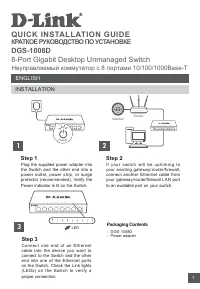
2 Hardware Installation D-Link Web Smart Switch User Manual 2 Hardware Installation This chapter provides unpacking and installation information for the D-Link Web-Smart Switch. Step 1: Unpacking Open the shipping carton and carefully unpack its contents. Please consult the packing list located in t...
Page 12 - pecified by the manufacturer.; Step 3 – Plugging in the AC Power Cord
2 Hardware Installation D-Link Web Smart Switch User Manual Then, use the screws provided with the equipment rack to mount the switch in the rack. Figure 2.3 – Mount the Switch in the rack or chassis Please be aware of following safety Instructions when installing: t in an environment compatible wit...
Page 13 - Power Failure
2 Hardware Installation D-Link Web Smart Switch User Manual Power Failure As a precaution, the switch should be unplugged in case of power failure. When power is resumed, plug the switch back in. 8
Page 14 - Getting; Started; Getting Started; Management Options
3 Getting Started D-Link Web Smart Switch User Manual 3 Getting Started This chapter introduces the management interface of D-Link Web-Smart Switch. Management Options The D-Link Web Smart Switch can be managed through any port on the device by using the Web-based Management, or through any PC using...
Page 15 - Login Web-based Management; Smart Wizard; Configuration; SmartConsole Utility
3 Getting Started D-Link Web Smart Switch User Manual Login Web-based Management In order to login and configure the switch via an Ethernet connection, the PC must have an IP address in the same subnet as the switch. For example, if the switch has an IP address of 10.90.90.90 , the PC should have an...
Page 16 - Please be sure to uninstall any existing
3 Getting Started D-Link Web Smart Switch User Manual NOTE: Please be sure to uninstall any existing SmartConsole Utility from your PC before installing the latest SmartConsole Utility. Option 1: Follow these steps to install the SmartConsole Utility via the autorun program on the installation CD. 1...
Page 17 - SmartConsole; Utility; SmartConsole Settings
4 SmartConsole Utility D-Link Web Smart Switch User Manual 4 SmartConsole Utility The D-Link SmartConsole Utility allows the administrator to quickly discover all D-Link smart switches, which are in the same domain of the PC, collect traps and log messages, and quick access to basic configurations o...
Page 19 - Help; Device Configuration
4 SmartConsole Utility D-Link Web Smart Switch User Manual Monitor Save: Records the setting of the Device List as default for the next time the SmartConsole Utility is used. Monitor Save As: Records the setting of the Device List in an appointed filename and file path. Monitor Load: Manually load a...
Page 20 - Device Password Manager; Multi Firmware Upgrade
4 SmartConsole Utility D-Link Web Smart Switch User Manual Figure 4.7 – SmartConsole Device Settings Device Password Manager Select a switch from the Device List. Click on this icon to launch the Device Password Manager window. Here you can enter a new password and confirm it. Figure 4.8 – SmartCons...
Page 21 - Do not disconnect the PC or remove; Web Access; Click the; Discovery; the; Device List
4 SmartConsole Utility D-Link Web Smart Switch User Manual CAUTION: Do not disconnect the PC or remove the power cord from the device until the upgrade completes. The software may be corrupted because of the incomplete firmware upgrade. DHCP Refresh: If a DHCP-client enabled switch in the Device Lis...
Page 22 - Device Group Interval:
4 SmartConsole Utility D-Link Web Smart Switch User Manual Definitions of the Device List features: Monitor: Checking the Monitor box and the SmartConsole will collect the trap and log data from the device. The in the monitor means the device was discovered by SmartConsole. Click the icon to have th...
Page 23 - Configuration; Smart Wizard Configuration; If you are not changing the settings, click on; Exit; to go back to the main page.
5 Configuration D-Link Web Smart Switch User Manual 5 Configuration The features and functions of the D-Link Web Smart Switch can be configured for optimum use through the Web-based Management Utility. Smart Wizard Configuration After a successful login, the Smart Wizard will guide you through essen...
Page 24 - SNMP; and then click; Apply; to make it effective.; Changing the system IP address will
5 Configuration D-Link Web Smart Switch User Manual Figure 5.2 – Password in Smart Wizard SNMP The SNMP Setting allows you to quickly enable/disable the SNMP function. The default SNMP Setting is Disabled. Click Enabled and then click Apply to make it effective. Figure 5.3 – SNMP in Smart Wizard NOT...
Page 25 - If you want to change the settings, click; OK; and start a new web browser.
5 Configuration D-Link Web Smart Switch User Manual If you want to change the settings, click OK and start a new web browser. Figure 5.4 – Confirm the changes of IP address in Smart Wizard 20
Page 26 - Web-based Management
5 Configuration D-Link Web Smart Switch User Manual Web-based Management After clicking the Exit button in Smart Wizard you will see the screen below: Figure 5.5 – Web-based Management The above image is the Web-based Management screen. The three main areas are the Tool Bar on top, the Function Tree...
Page 27 - Tool Bar > Save Menu; The Save Menu provides Save Configuration and Save Log functions.; Tool Bar > Tool Menu; Provide a safe way to reboot the system. Click
5 Configuration D-Link Web Smart Switch User Manual Tool Bar > Save Menu The Save Menu provides Save Configuration and Save Log functions. Figure 5.6 – Save Menu Save Configuration Select to save the entire configuration changes you have made to the device to switch’s non-volatile RAM. Figure 5.7...
Page 29 - Tool Bar > Smart Wizard
5 Configuration D-Link Web Smart Switch User Manual HTTP: Backup or upgrade the firmware to or from your local PC drive. Click Backup to save the firmware to your disk. Click Browse to browse your inventories for a saved firmware file. Click Upgrade after selecting the firmware file you want to rest...
Page 31 - Function Tree
5 Configuration D-Link Web Smart Switch User Manual Function Tree All configuration options on the switch are accessed through the Setup menu on the left side of the screen. Click on the setup item that you want to configure. The following sections provide more detailed description of each feature a...
Page 33 - Be sure to adjust port speed settings
5 Configuration D-Link Web Smart Switch User Manual Figure 5.21 – System > Port Settings Speed: Gigabit Fiber connections can operate in 1000M Full Force Mode, Auto Mode or Disabled. Copper connections can operate in Forced Mode settings (1000M Full, 100M Full, 100M Half, 10M Full, 10M Half), Aut...
Page 36 - Click to delete the VLAN group.; Untag; . A port can be untagged in only one VID. To save the VID group, click; to implement
5 Configuration D-Link Web Smart Switch User Manual Delete VID: Click to delete the VLAN group. Add New VID: Click to create a new VID group, assigning ports from 01 to 28 as Untag , Tag , or Not Member . A port can be untagged in only one VID. To save the VID group, click Apply. You may change the ...
Page 37 - VLAN > Voice VLAN > Voice VLAN Global Settings; Voice VLAN Global Settings
5 Configuration D-Link Web Smart Switch User Manual By default, the Management VLAN is disabled. You can select any existing VLAN as the management VLAN when this function is enabled. There can only be one management VLAN at a time. Figure 5.29 – Configuration > 802.1Q Management VLAN VLAN > V...
Page 38 - Disabled
5 Configuration D-Link Web Smart Switch User Manual OUI Vendor Mnemonic Name 00:E0:BB 3Com 3com 00:03:6B Cisco cisco 00:E0:75 Veritel veritel 00:D0:1E Pingtel pingtel 00:01:E3 Siemens siemens 00:60:B9 NEC/ Philips nec&philips 00:0F:E2 Huawei-3COM huawei&3com 00:09:6E Avaya avaya Default OUI:...
Page 39 - Search
5 Configuration D-Link Web Smart Switch User Manual Note: Voice VLAN has higher priority than any other features even QoS. Therefore the voice traffic will be operated according to Voice VLAN setting and not impacted by QoS feature. Note: It is recommended setting the highest priority for Voice VLAN...
Page 40 - IP Surveillance Devices
5 Configuration D-Link Web Smart Switch User Manual VLAN page. The member port you configured in 802.1Q VLAN setting page will be the static member port of Auto Surveillance VLAN. Priority: The 802.1p priority levels of the traffic in the Auto Surveillance VLAN. The possible values are Highest, High...
Page 41 - Enabled
5 Configuration D-Link Web Smart Switch User Manual RX (receive) mode: Duplicates the data that is received from the source port and forwards it to the Target Port. Click “all” to include all ports into port mirroring. Port. Click “all” to include all ports into port mirroring. TX/RX (transmit and r...
Page 45 - L2 Functions > Link Aggregation > LACP Port Settings; pply
5 Configuration D-Link Web Smart Switch User Manual Figure 5.41 – L2 Functions > Link Aggregation > Port Trunking NOTE: Each combined trunk port must be connected to devices within the same VLAN group. L2 Functions > Link Aggregation > LACP Port Settings The LACP Port Settings is used to...
Page 54 - Displays the port description.; of Normal column to display more information.; View; of Detailed column to display detail information.; L2 Functions > LLDP > LLDP Remote Port Table; to display additional information.
5 Configuration D-Link Web Smart Switch User Manual Port Description: Displays the port description. Click View of Normal column to display more information. Figure 5.58 – L2 Functions > LLDP > LLDP Local Port Normal Table Click View of Detailed column to display detail information. Figure 5.5...
Page 55 - View Normal; View Detailed; and the following page displays.
5 Configuration D-Link Web Smart Switch User Manual Figure 5.60 – L2 Functions > LLDP > LLDP Remote Port Table To view the settings for a remote port, click View Normal and the following page displays. Figure 5.61 – L2 Functions > LLDP > LLDP Remote Port Normal Table To view the detail s...
Page 57 - Displays the total number of LLDP frames received on the port.
5 Configuration D-Link Web Smart Switch User Manual RxPort FramesDiscarded – Displays the total discarded frame number of LLDP frames received on the port. RxPort FramesErrors – Displays the Error frame number of LLDP frames received on the port. RxPort Frames – Displays the total number of LLDP fra...
Page 58 - WRR
5 Configuration D-Link Web Smart Switch User Manual The following figure displays the status of Quality of Service priority levels of each port, higher priority means the traffic from this port will be first handled by the switch. For packets that are untagged, the switch will assign the priority de...
Page 60 - Security > Storm Control; User can select the; for the settings to take effect.; Security > ARP Spoofing Prevention
5 Configuration D-Link Web Smart Switch User Manual Figure 5.69 – Security > Safeguard Engine Security > Storm Control The Storm Control feature provides the ability to control the receive rate of broadcast, multicast, and unknown unicast packets. Once a packet storm has been detected, the Swi...
Page 62 - When SSL is enabled, it will take longer; Security > Smart Binding > Smart Binding Settings; and; DHCP Snooping; Enabled –; Enable Smart Binding with related configurations to the ports
5 Configuration D-Link Web Smart Switch User Manual Figure 5.73 – Security > SSL Settings NOTE: When SSL is enabled, it will take longer time to open a web page due to encryption. After saving configuration, please wait around 10 seconds for the system summery page. Security > Smart Binding &g...
Page 63 - ARP Inspection
5 Configuration D-Link Web Smart Switch User Manual Disabled – Disable Smart Binding. Packet Inspection: Specifies ARP Inspection or IP+ARP Inspection for the IP packets. If ARP inspection is selected, the Switch will inspect incoming ARP packets and compare them with the Switch’s Smart Binding whit...
Page 65 - Enter the Key a second time for confirmation.
5 Configuration D-Link Web Smart Switch User Manual Figure 5.78 – Security > 802.1X > 802.1X Settings By default, 802.1X is disabled. To use EAP for security, select enabled and set the 802.1X Global Settings for the Radius Server and applicable authentication information. RADIUS Server IP: Th...
Page 66 - Permit
5 Configuration D-Link Web Smart Switch User Manual ACL > ACL Wizard Access Control List (ACL) allows you to establish criteria to determine whether or not the Switch will forward packets based on the information contained in each packet's header. This criteria can be specified on a basis of the ...
Page 67 - ACL > ACL Profile List
5 Configuration D-Link Web Smart Switch User Manual NOTE: Be careful when configuring ACL rules, an inappropriate ACL rule may cause management access failure. ACL > ACL Profile List The ACL Profile List provides information for configuring ACL Profiles manually. ACL profiles are attached to inte...
Page 74 - no authorization
5 Configuration D-Link Web Smart Switch User Manual Figure 5.90 – SNMP > SNMP > SNMP User Table User Name: Enter a SNMP user name of up to 32 characters. Group Name: Specify the SNMP group of the SNMP user. SNMP Version: Specify the SNMP version of the user. Only SNMPv3 encrypts the messages. ...
Page 75 - Add
5 Configuration D-Link Web Smart Switch User Manual Figure 5.91 – SNMP > SNMP > SNMP Group Table SNMP > SNMP > SNMP View This page allows you to maintain SNMP views to community strings that define the MIB objects which can be accessed by a remote SNMP manager. Figure 5.92 – SNMP > SN...
Page 77 - user defined RMON events.; Delta value –
5 Configuration D-Link Web Smart Switch User Manual Click Add to make the configurations take effects. SNMP > RMON > RMON History The RMON History Control Configuration page contains information about samples of data taken from ports. For example, the samples may include interface definitions ...
Page 80 - Monitoring > System Log
5 Configuration D-Link Web Smart Switch User Manual NOTE: Please be sure that Power Saving feature is disabled before enabling Cable Diagnostics function. Monitoring > System Log The System Log page provides information about system logs, including information when the device was booted, how the ...
Page 81 - Line Interface; Command Line Interface; To connect a switch via TELNET:; HyperTerminal; Logging on to the Command Line Interface:; Command; config
6 Command Line Interface D-Link Web Smart Switch User Manual 6 Command Line Interface The D-Link Web Smart Switch allows a computer or terminal to perform some basic monitoring and configuration tasks by using the Command Line Interface (CLI) via TELNET protocol. To connect a switch via TELNET: 1. M...
Page 82 - download; filename
6 Command Line Interface D-Link Web Smart Switch User Manual Each command is listed in detail, as follows: ? Purpose To display a list of commands. Syntax ? Description The ? command displays a list of commands of the switch. Parameters None. Restrictions None. Example usage: To display a list of co...
Page 83 - The copy operation was completed successfully; upload
6 Command Line Interface D-Link Web Smart Switch User Manual file is not at the root directory of the TFTP server. Restrictions None. Example usage: To download a firmware file: DGS-1210-52> download firmware_fromTFTP 1.1.1.23 1\dgs_1210-10032.ros 01–Jan–2000 01:19:48 %COPY–I–FILECPY: Files Copy ...
Page 84 - completed success fully; config ipif system; dhcp; logout
6 Command Line Interface D-Link Web Smart Switch User Manual file on the TFTP server. You need to specify the DOS path if the file is not at the root directory of the TFTP server. Restrictions None. Example usage: To upload a firmware file: DGS-1210-52>upload firmware_toTFTP 1.1.1.23 1\running—co...
Page 85 - ping; reboot
6 Command Line Interface D-Link Web Smart Switch User Manual Description The logout command terminates the current user’s session on the Switch’s console. Parameters None. Restrictions None. Example usage: To terminate the current user’s console session: DGS-1210-52> logout NOTE: Save your config...
Page 86 - reset config
6 Command Line Interface D-Link Web Smart Switch User Manual Example usage: To restart the Switch: DGS-1210-52> reboot % Device will reboot, please wait a few minutes to re-login. DGS-1210-52> reset config Purpose To reset the Switch to the factory default settings. Syntax reset config Descrip...
Page 87 - show switch
6 Command Line Interface D-Link Web Smart Switch User Manual show switch Purpose To display information about the Switch. Syntax show switch Description The show switch command displays the status of the switch. Parameters None. Restrictions None. Example usage: To display the switch information: DG...
Page 88 - save command; debug info
6 Command Line Interface D-Link Web Smart Switch User Manual Description The save command saves the configuration changes to the memory. Parameters None. Restrictions None. Example usage: To save the Switch’s current configuration to non-volatile RAM: DGS-1210-52> save Building configuration ... ...
Page 89 - Total Mac Addresses displayed: 1
6 Command Line Interface D-Link Web Smart Switch User Manual Total Mac Addresses displayed: 1 DGS-1210-52> 84
Page 90 - Appendix A; - Ethernet Technology; Appendix A - Ethernet Technology; Gigabit Ethernet Technology
Appendix A - Ethernet Technology D-Link Web Smart Switch User Manual 8 8 5 5 Appendix A - Ethernet Technology This chapter will describe the features of the D-Link Web Smart Switch and provide some background information about Ethernet/Fast Ethernet/Gigabit Ethernet switching technology. Gigabit Eth...
Page 91 - Technical Specifications; Appendix B - Technical Specifications; Hardware Specifications
Appendix B - Technical Specifications D-Link Web Smart Switch User Manual Appendix B - Technical Specifications Hardware Specifications Key Components / Performance Switching Capacity: - DGS-1210-20: 40Gbps - DGS-1210-28: 56Gbps - DGS-1210-28P: 56Gbps - DGS-1210-52: 104Gbps Max. Forwarding Rate - DG...
Page 92 - Appendix B; - Technical Specifications
Appendix B - Technical Specifications D-Link Web Smart Switch User Manual LLDP L2 Multicast Filtering D-Link Green Technology Power Saving: Enabled by default to save power: - By Link Status: Drastically save power when the switch port link is down. For example, no PC connection or the connected PC ...
Page 93 - Appendix C –; Rack mount Instructions; Appendix C – Rack mount Instructions
Appendix C – Rack mount Instructions D-Link Web Smart Switch User Manual Appendix C – Rack mount Instructions Safety Instructions - Rack Mount Instructions - The following or similar rack-mount instructions are included with the installation instructions: A) Elevated Operating Ambient - If installed...