Page 2 - D-Link Smart Managed Switch User Manual; Table of Contents
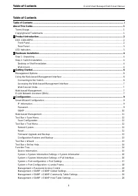
Table of Contents D-Link Smart Managed Switch User Manual i i Table of Contents Table of Contents ............................................................................................................................................. i About This Guide ............................................
Page 4 - iii
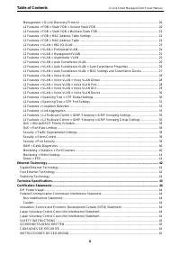
Table of Contents D-Link Smart Managed Switch User Manual iii ISTRUZIONI PER LA SICUREZZA ............................................................................................................. 46 VEILIGHEIDSINFORMATIE ..............................................................................
Page 5 - About This Guide; The model you have purchased may; NOTE; indicates important information that; CAUTION; indicates potential property damage; Copyright and Trademarks
About This Guide D-Link Smart Managed Switch User Manual 1 About This Guide This guide provides step-by-step instructions on how install the D-Link DGS-1100-08PD Smart Managed Switches, how to use the Web Utility, and how to perform web-based management functions. Note: The model you have purchased ...
Page 6 - Product; Introduction; Product Introduction; Flexible Port Configurations.; Front Panel; 0/100/1000 Mbps ports to connect Ethernet devices to the switch.
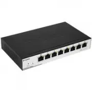
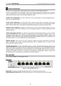
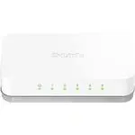
1 Product Introduction D-Link Smart Managed Switch User Manual 2 1 Product Introduction Thank you and congratulations on the purchase of your new D-Link Smart Managed Switch. D-Link's next generation Smart Managed switch series blends plug-and-play simplicity with exceptional value and reliability f...
Page 7 - Rear Panel; LED Indicators; Location
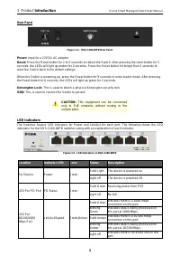
1 Product Introduction D-Link Smart Managed Switch User Manual 3 3 Rear Panel Figure 1.4 – DGS-1100-08PD Rear Panel Power: Input for a 12V/1A AC adapter. Reset: Press the Reset button for 1 to 5 seconds to reboot the Switch. After pressing the reset button for 5 seconds, the LEDs will light up amber...
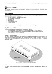
Page 8 - Hardware; Installation; Hardware Installation; One AC external power adapter; Step 2: Switch Installation; Do not place heavy objects on the switch.; Desktop or Shelf Installation; Figure 2.1 – Attach the adhesive rubber pads to the bottom
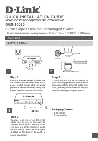
2 Hardware Installation D-Link Smart Managed Switch User Manual 4 2 Hardware Installation This chapter provides unpacking and installation information for your D-Link DGS-1100-08PD Smart Managed Switch. Step 1: Unpacking Open the shipping carton and carefully unpack its contents. Please consult the ...
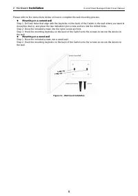
Page 9 - Mounting on a cement wall; Figure 2.2 – Wall mount installation
2 Hardware Installation D-Link Smart Managed Switch User Manual 5 5 Please refer to the instructions below on how to complete the wall-mounting process. Mounting on a cement wall Step 1: Drill two holes that align with the keyholes on the back of the Switch in the wall where you want to mount the ...
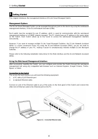
Page 10 - Getting; Started; Getting Started; Management Options; Connecting to the Switch; A PC with a RJ45 Ethernet port.; Figure 3.1 – Connected Ethernet cable
3 Getting Started D-Link Smart Managed Switch User Manual 6 3 Getting Started This chapter introduces the management interface of D-Link Smart Managed Switch. Management Options The D-Link Smart Managed Switch can be managed through any port on the device by using the web-based management interface,...
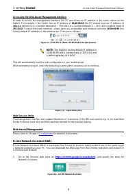
Page 11 - Accessing the Web-based Management Interface; Figure 3.3 – Logon Dialog Box; Web Session limite; Web-based Management; Configuration
3 Getting Started D-Link Smart Managed Switch User Manual 7 7 Accessing the Web-based Management Interface In order to access the management interface, the PC must have an IP address in the same subnet as the Switch. For example, if the Switch has an IP address of 10.90.90.90 , the PC should have an...
Page 12 - When the installation process has finished:
3 Getting Started D-Link Smart Managed Switch User Manual 8 2. Click ‘ADD TO CHROME’ button on the right hand side of the search results. 3. Click ‘Add app’ button in the pop-up window to install the D-Link Network Assistant in Chrome. 4. When the installation process has finished: (Option 1) Click ...
Page 13 - Configuration; Smart Wizard Configuration; Figure 4.1 – IP Information in Smart Wizard
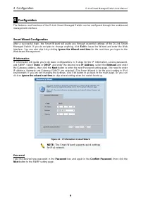
4 Configuration D-Link Smart Managed Switch User Manual 9 9 4 Configuration The features and functions of the D-Link Smart Managed Switch can be configured through the web-based management interface. Smart Wizard Configuration After a successful login, the Smart Wizard will guide you through essenti...
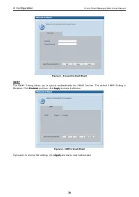
Page 14 - Figure 4.2 – Password in Smart Wizard; SNMP; and then click; to make it effective.; Figure 4.3 –SNMP in Smart Wizard; If you want to change the settings, click; Apply; and start a new web browser
4 Configuration D-Link Smart Managed Switch User Manual 10 Figure 4.2 – Password in Smart Wizard SNMP The SNMP Setting allows you to quickly enable/disable the SNMP function. The default SNMP Setting is Disabled. Click Enabled and then click Apply to make it effective. Figure 4.3 –SNMP in Smart Wiza...
Page 16 - Tool Bar > Save Menu; Figure 4.5 – Save Menu; Tool Bar > Tool Menu; Figure 4.7 – Tool Menu
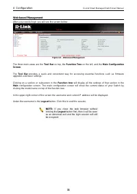
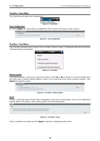
4 Configuration D-Link Smart Managed Switch User Manual 12 Tool Bar > Save Menu The Save Menu provides Save Configuration Figure 4.5 – Save Menu Save Configuration By clicking Apply , the current device configuration will be saved on the device’s flash memory. Figure 4.6 – Save Configuration Tool...
Page 17 - Figure 4.10 – Tool Menu > Firmware upgrade and Backup
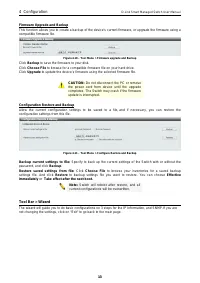
4 Configuration D-Link Smart Managed Switch User Manual 1 1 3 3 Firmware Upgrade and Backup This function allows you to create a backup of the device’s current firmware, or upgrade the firmware using a compatible firmware file. Figure 4.10 – Tool Menu > Firmware upgrade and Backup Click Backup to...
Page 18 - Tool Bar > Online Help; The Online Help provides two ways of online support:; User Guide; can offer an; Figure 4.13 – Online Help; Function Tree
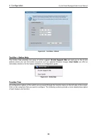
4 Configuration D-Link Smart Managed Switch User Manual 14 Figure 4.12 – Tool Menu > Wizard Tool Bar > Online Help The Online Help provides two ways of online support: D-Link Support Site will lead you to the D-Link website where you can find online resources such as updated firmware images; U...
Page 19 - Figure 4.14 –Function Tree; Device Information; Figure 4.15 – Device Information
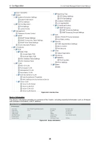
4 Configuration D-Link Smart Managed Switch User Manual 1 1 5 5 Figure 4.14 –Function Tree Device Information The Device Information provides an overview of the Switch, including essential information such as firmware and hardware information, and IP address. Figure 4.15 – Device Information
Page 20 - Figure 4.17 – System > System Information Settings > IPv4 Interface; Item
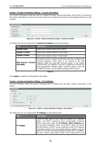
4 Configuration D-Link Smart Managed Switch User Manual 16 System > System Information Settings > System Information The System Information allows the user to configure the basic system information of the Switch. By entering the system information, the device can more easily be recognized from...
Page 21 - Auto
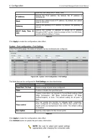
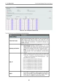
4 Configuration D-Link Smart Managed Switch User Manual 1 1 7 7 user only can setup DHCP Retry Time IP Address Specify the IPv4 address. By default, the IP address is 10.90.90.90 Mask Specify the subnet mask of IP address. By default, the subnet mask is 255.0.0.0 Gateway Specify the gateway of IP ad...
Page 22 - Figure 4.20 – Management > Password Access Control
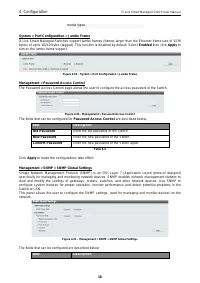
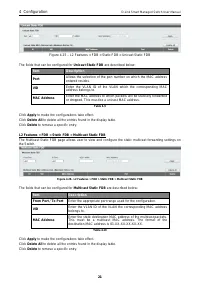
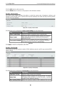
4 Configuration D-Link Smart Managed Switch User Manual 18 media types. System > Port Configuration > Jumbo Frame D-Link Smart Managed Switches support jumbo frames (frames larger than the Ethernet frame size of 1536 bytes) of up to 10240 bytes (tagged). This function is disabled by default. S...
Page 23 - SNMP Global Settings; Figure 4.22–Management > SNMP > SNMP Community Table Settings
4 Configuration D-Link Smart Managed Switch User Manual 1 1 9 9 SNMP Global Settings SNMP Global State Specify to enable or disable the SNMP feature. The default setting is Disabled . Trap Settings Trap Global State Enable or disable SNMP trap notifications from client devices. Disabling this option...
Page 24 - SNMPv2c
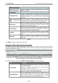
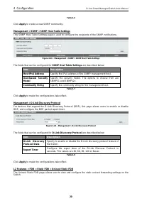
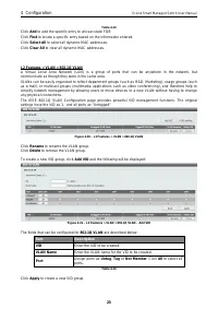
4 Configuration D-Link Smart Managed Switch User Manual 20 Table 4.6 Click Apply to create a new SNMP community. Management > SNMP > SNMP Host Table Settings This SNMP Host Table Settings page is used to configure the recipients of the SNMP notifications. Figure 4.23 – Management > SNMP >...
Page 28 - disabled
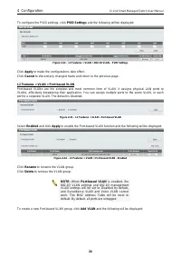
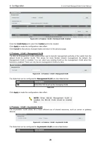
4 Configuration D-Link Smart Managed Switch User Manual 24 To configure the PVID settings, click PVID Settings and the following will be displayed: Figure 4.32 – L2 Features > VLAN > 802.1Q VLAN – PVID Settings Click Apply to make the configurations take effect. Click Cancel to discard any cha...
Page 30 - Global Settings
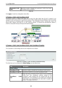
4 Configuration D-Link Smart Managed Switch User Manual 26 Asymmetric VLAN State Specify to enable or disable the Asymmetric VLAN of the Switch. The default value is disabled . Table 4.16 Click Apply to make the configurations take effect. L2 Features > VLAN > Auto Surveillance VLAN Surveillan...
Page 31 - User-defined MAC Settings
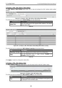
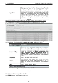
4 Configuration D-Link Smart Managed Switch User Manual 2 2 7 7 Aging Time Enter the aging time value here. This is used to configure the aging time for aging out the surveillance VLAN dynamic member ports. The range is from 1 to 65535 minutes. When the last surveillance device connected to the port...
Page 32 - Figure 4.40 – Auto Surveillance VLAN Summary; The fields that can be configured for; Voice VLAN Global
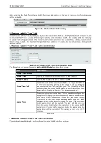
4 Configuration D-Link Smart Managed Switch User Manual 28 After selecting the Auto Surveillance VLAN Summary tab option, at the top of the page, the following page will be available. Figure 4.40 – Auto Surveillance VLAN Summary L2 Features > VLAN > Voice VLAN Voice VLAN is a feature that allo...
Page 33 - Voice VLAN Port
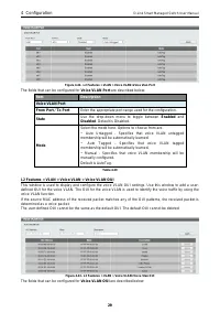
4 Configuration D-Link Smart Managed Switch User Manual 2 2 9 9 Figure 4.42– L2 Features > VLAN > Voice VLAN>Voice Vlan Port The fields that can be configured for Voice VLAN Port are described below: Item Description Voice VLAN Port From Port / To Port Enter the appropriate port range used ...
Page 34 - Voice vlan OUI; OUI
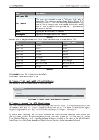
4 Configuration D-Link Smart Managed Switch User Manual 30 Item Description Voice vlan OUI OUI Address The user can manually create a Telephony OUI with a description. The maximum number of user defined OUIs is 5. It will occupy one ACL rule when selecting user defined OUI by default, and to configu...
Page 35 - Figure 4.45– L2 Features > Spanning Tree > STP Global Settings; Spanning Tree State
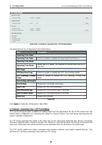
4 Configuration D-Link Smart Managed Switch User Manual 3 3 1 1 Figure 4.45– L2 Features > Spanning Tree > STP Global Settings The fields that can be configured are described below: Item Description Spanning Tree State Spanning Tree State Select to enable or disable the Spanning Tree Protocol....
Page 36 - Figure 4.46 – L2 Features > Spanning Tree > STP Port Settings; The fields that can be configured are described below:; Click; to make the configurations take effect.; Refresh; times out. Loopback Detection can also
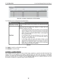
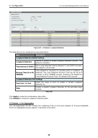
4 Configuration D-Link Smart Managed Switch User Manual 32 Figure 4.46 – L2 Features > Spanning Tree > STP Port Settings The fields that can be configured are described below: Item Description From Port / To Port Select the range of ports to be included in the spanning tree port group. Port Fa...
Page 37 - Figure 4.47 – L2 Features > Loopback Detection; Loopback Detection Global Settings; Loopback Detection; Loopback Detection Port Settings; State
4 Configuration D-Link Smart Managed Switch User Manual 3 3 3 3 Figure 4.47 – L2 Features > Loopback Detection The fields that can be configured are described below: Item Description Loopback Detection Global Settings Loopback Detection Specify to enable or disable loopback detection function. Th...
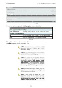
Page 38 - Figure 4.48 – L2 Features > Link Aggregation; Link Aggregation Global Settings
4 Configuration D-Link Smart Managed Switch User Manual 34 Figure 4.48 – L2 Features > Link Aggregation The fields that can be configured for Link Aggregation are described below: Item Description Link Aggregation Global Settings Link Aggregation Specify to enable or disable the Link Aggregation ...
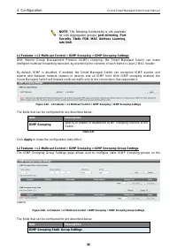
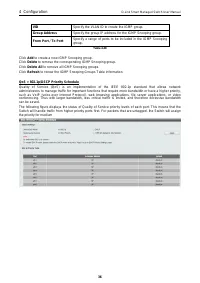
Page 39 - IGMP Snooping Static Group Settings
4 Configuration D-Link Smart Managed Switch User Manual 3 3 5 5 NOTE: The following functionality is not available for Link Aggregation groups: port mirroring , Port Security , Static FDB , MAC Address Learning , rate limit . L2 Features > L2 Multicast Control > IGMP Snooping > IGMP Snoopin...
Page 41 - Select QoS mode
4 Configuration D-Link Smart Managed Switch User Manual 3 3 7 7 Figure 4.51 – QoS > 802.1p/DSCP Default Priority The fields that can be configured are described below: Item Description Global Settings Select QoS mode D-Link Smart Managed Switch allows the user to prioritize the traffic based on t...
Page 42 - Figure 4.53– Security > Traffic Segmentation Settings
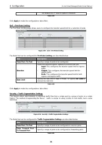
4 Configuration D-Link Smart Managed Switch User Manual 38 The default DSCP value to queue is medium Table 4.29 Click Apply to make the configurations take effect. QoS > Port Rate Limiting The Port Rate Limiting page allows users to configure the transfer speed limit for a selection of ports. F...
Page 45 - Figure 4.58 – Monitoring > Mirror Settings
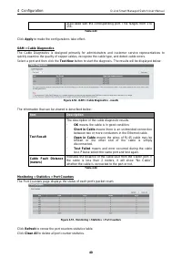
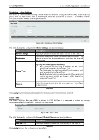
4 Configuration D-Link Smart Managed Switch User Manual 4 4 1 1 Monitoring > Mirror Settings Port Mirror is a method of monitoring network traffic that forwards a copy of each incoming and/or outgoing packet from one port of the Switch to another port, where the packet can be studied. This enable...
Page 46 - Ethernet Technology; Gigabit Ethernet Technology
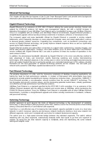
Ethernet Technology D-Link Smart Managed Switch User Manual 42 Ethernet Technology This chapter will describe the features of the D-Link Smart Managed Switch and provide some background information about Ethernet/Fast Ethernet/Gigabit Ethernet switching technology. Gigabit Ethernet Technology Gigabi...
Page 47 - Technical Specifications; Key Components / Performance; Store and Forward; Port Functions; - Back Pressure for Half-Duplex mode; Physical & Environment; Maximum
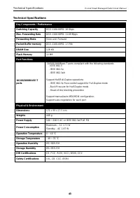
Technical Specifications D-Link Smart Managed Switch User Manual 4 4 3 3 Technical Specifications Key Components / Performance Switching Capacity DGS-1100-08PD: 16 Gbps Max. Forwarding Rate DGS-1100-08PD: 11.09 Mpps Forwarding Mode Store and Forward Packet Buffer memory DGS-1100-08PD: 1.5 Mb DRAM Si...
Page 48 - Certification Statements; ErP Power Usage; Reorient or relocate the receiving antenna.; Japan Voluntary Control Council for Interference Statement; Japan Voluntary Control Council for Interference Statement
Certification Statements D-Link Smart Managed Switch User Manual 44 Certification Statements ErP Power Usage This device is an Energy Related Product (ErP) with High Network Availability (HiNA), and automatically switches to a power-saving Network Standby mode within 1 minute of no packets being tra...
Page 49 - SAFETY INSTRUCTIONS; Keep the product away from radiators and other heat sources.; SICHERHEITSVORSCHRIFTEN; Éloignez le produit des radiateurs et autres sources de chaleur.; INSTRUCCIONES DE SEGURIDAD
Certification Statements D-Link Smart Managed Switch User Manual 4 4 5 5 SAFETY INSTRUCTIONS The following general safety guidelines are provided to help ensure your own personal safety and protect your product from potential damage. Remember to consult the product user instructions for more details...
Page 50 - ISTRUZIONI PER LA SICUREZZA; Tenere il prodotto lontano da caloriferi e altre fonti di calore.; VEILIGHEIDSINFORMATIE; ENGLISH
Certification Statements D-Link Smart Managed Switch User Manual 46 • La electricidad estática puede resultar nociva para los componentes electrónicos. Descargue la electricidad estática de su cuerpo (p. ej., tocando algún metal sin revestimiento conectado a tierra) antes de tocar el producto. • No ...
Page 52 - Breng een bezoek aan
Certification Statements D-Link Smart Managed Switch User Manual 48 Este símbolo en el producto o el embalaje significa que, de acuerdo con la legislación y la normativa local, este producto no se debe desechar en la basura doméstica sino que se debe reciclar. Llévelo a un punto de recogida designad...
Page 55 - PORTUGUÊS
Certification Statements D-Link Smart Managed Switch User Manual 5 5 1 1 Den här symbolen på produkten eller förpackningen betyder att produkten enligt lokala lagar och föreskrifter inte skall kastas i hushållssoporna utan i stället återvinnas. Ta den vid slutet av dess livslängd till en av din loka...