Artusi AFG1206X - Manuals
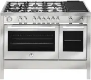
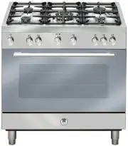
User Manual Artusi AFG1206X


Summary
3 461308300_000 12/2013 CONTENTS ASSISTANCE AND SPARE PARTS 3 IMPORTANT NOTES AND PRECAUTIONS FOR USE 4-6 DESCRIPTION OF THE APPLIANCE 7-10 INSTRUCTIONS FOR THE USER 10-18 INSTRUCTIONS FOR THE INSTALLER 19-27 TROUBLESHOOTING 28 TECHNICAL FEATURES 28-29 Before this appliance left the factory it was t...
4 IMPORTANT NOTES AND PRECAUTIONS FOR USE You have purchased one of our products for which we thank you. We are confident that this new appliance, modern, functional and practical, made with top quality materials, will meet all your demands. This new appliance is easy to use but before installing an...
6 IMPORTANT NOTES AND PRECAUTIONS FOR USE • The appliance is not intended to be operated by means of an external timer or separate remote-control system • Ensure that the appliance is switched off before replacing the lamp to avoid the possibility of electric shock.. • The cookers can be equipped wi...
Artusi Ovens Manuals
-
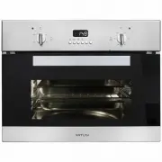 Artusi ACSO45X
User Manual
Artusi ACSO45X
User Manual
-
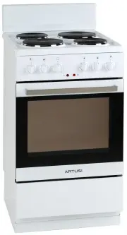
 Artusi AFC547W
User Manual
Artusi AFC547W
User Manual
-
 Artusi AFC607B
User Manual
Artusi AFC607B
User Manual
-
 Artusi AFC607W
User Manual
Artusi AFC607W
User Manual
-
 Artusi AFC607X
User Manual
Artusi AFC607X
User Manual
-
 Artusi AFDC5470W
User Manual
Artusi AFDC5470W
User Manual
-
 Artusi AFDE5470W
User Manual
Artusi AFDE5470W
User Manual
-
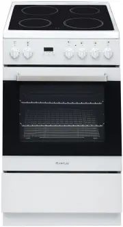
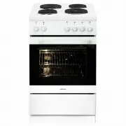
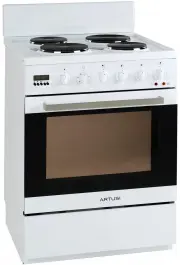
 Artusi AFE504W
User Manual
Artusi AFE504W
User Manual
-
 Artusi AFE544W
User Manual
Artusi AFE544W
User Manual
-
 Artusi AFE547W
User Manual
Artusi AFE547W
User Manual
-
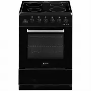
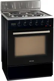 Artusi AFE607B
User Manual
Artusi AFE607B
User Manual
-
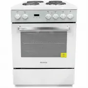
 Artusi AFE607W
User Manual
Artusi AFE607W
User Manual
-
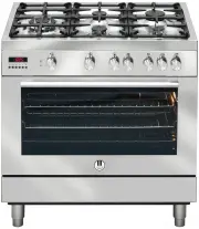 Artusi AFG900X
User Manual
Artusi AFG900X
User Manual
-
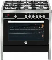 Artusi AFG910B
User Manual
Artusi AFG910B
User Manual
-
 Artusi AFG910W
User Manual
Artusi AFG910W
User Manual
-
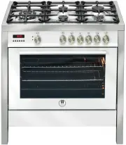
 Artusi AFG910X
User Manual
Artusi AFG910X
User Manual
-
 Artusi AFG911X
User Manual
Artusi AFG911X
User Manual
-
 Artusi AFG915B
User Manual
Artusi AFG915B
User Manual
-
 Artusi AFG915X
User Manual
Artusi AFG915X
User Manual
-
 Artusi AFG940X
User Manual
Artusi AFG940X
User Manual