Page 2 - Tools and Parts; Tools Needed
2 MICROWAVE HOOD COMBINATION SAFETY INSTALLATION REQUIREMENTS Tools and Parts Tools Needed Gather the required tools and parts before starting installation. Read and follow the instructions provided with any tools listed here. ■ Measuring tape ■ Pencil ■ Masking tape or thumbtacks ■ Scissors ■ No. 2...
Page 3 - Special Requirements; For Wall Venting Installation Only:; Installation Dimensions; Product Dimensions
3 Remove Cardboard Template The cardboard piece from the top of the microwave oven packaging is perforated. The piece inside the perforation is for use as a rear wall template and upper cabinet template. 1. Cut along the perforation to separate the template from the rest of the cardboard packaging. ...
Page 4 - Electrical Requirements; GROUNDING INSTRUCTIONS; WARNING
4 Electrical Requirements Observe all governing codes and ordinances. Required: ■ A 120 V, 60 Hz, AC only, 15 or 20 A electrical supply with a fuse or circuit breaker Recommended: ■ A time-delay fuse or time-delay circuit breaker ■ A separate circuit serving only this microwave oven GROUNDING INSTRU...
Page 5 - INSTALLATION INSTRUCTIONS; Remove Mounting Plate; Wall Venting Installation Only
5 INSTALLATION INSTRUCTIONS Remove Mounting Plate Depending on your model, the mounting plate may be in the foam packaging, or it may be attached to the back of the microwave oven. NOTE: To avoid possible damage, cover the work surface. 1. Remove any remaining contents from the microwave oven cavity...
Page 7 - Roof Venting Installation Only
7 13. Secure damper plate with two screws removed in Step 1. Roof Venting Installation Only 1. Repeat Step 1 from “Wall Venting Installation Only.” 2. Repeat Step 2 from “Wall Venting Installation Only.” 3. Repeat Step 3 from “Wall Venting Installation Only.” 4. Repeat Step 4 from “Wall Venting Inst...
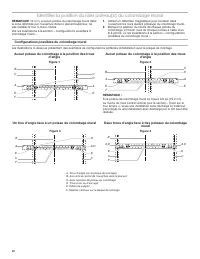
Page 8 - Possible Wall Stud Confi gurations; Figure 1
8 Locate Wall Stud(s) NOTE: If no wall studs exist within the cabinet opening, do not install the microwave oven. See illustrations in “Possible Wall Stud Confi gurations.” 1. Using a stud fi nder, locate the edges of the wall stud(s) within the opening. 2. Mark the center of each stud, and draw a p...
Page 9 - Mark Rear Wall
9 Mark Rear Wall The microwave oven must be installed on a minimum of one wall stud, preferably two, using a minimum of one lag screw, preferably two. 1. Using measuring tape, fi nd and clearly mark the vertical centerline of the opening. 2. Align the center markers on the cardboard template (carton...
Page 10 - Drill Holes in Rear Wall; Installation for Wall Stud at One End Hole (Figure 3); Attach Mounting Plate to Wall; No Wall Studs at End Holes (Figures 1 and 2)
10 Drill Holes in Rear Wall In addition to being installed on at least one wall stud, the mounting plate must attach to the wall at both end holes. If the end holes are not over wall studs, use two 3/16-24 x 3" round-head bolts with toggle nuts; if one end hole is over a wall stud, use one lag s...
Page 11 - Prepare Upper Cabinet; For Roof Venting Installation Only:; Install Damper Assembly
11 Prepare Upper Cabinet 1. Disconnect power to outlet. 2. Remove all contents from upper cabinet. 3. Place cardboard template against the bottom of the upper cabinet, make sure the template centerline aligns with the vertical centerline on the rear wall.The “rear wall” arrows must be against the re...
Page 12 - Install the Microwave Oven; Excessive Weight Hazard
12 Install the Microwave Oven IMPORTANT: The control side of the microwave oven is the heavy side. Handle the microwave oven gently. 1. Remove the two packing spacers from the top of the vent grille before using the microwave oven. NOTE: Depending on your model, it may not have packing spacers. If i...
Page 13 - For Roof Venting Installation Only; Complete Installation; Electrical Shock Hazard
13 NOTE: Avoid damage to the mounting nut, screw the bolts into the mounting nut holes around 15-20 mm by hand fi rst, make sure the bolts thread in properly. Then tighten with tools. For Roof Venting Installation Only 1. Insert damper assembly through the cabinet cutout so that the long tab of the ...
Page 14 - VENTING DESIGN SPECIFICATIONS; For optimal venting installation, we recommend:; Recommended Standard Fittings
14 VENTING DESIGN SPECIFICATIONS This section is intended for architectural designer and builder/ contractor reference only. NOTES: ■ Vent materials needed for installation are not provided with microwave hood combination. ■ We do not recommend using a fl exible metal vent. ■ To avoid possible produ...
Page 15 - Recommended Vent Length; total; ASSISTANCE; Replacement Parts; Accessories
15 Recommended Vent Length A 3 1 ⁄ 4 " x 10" (8.3 x 25.4 cm) rectangular or 6" (15.2 cm) round vent should be used. The total length of the vent system including straight vent, elbow(s), transitions and wall or roof caps must not exceed the equivalent of 140 ft (42.7 m) for either type o...
Page 16 - Outillage et pièces; Outillage nécessaire; Matériaux nécessaires
16 SÉCURITÉ DE L’ENSEMBLE FOUR À MICRO-ONDES/HOTTE EXIGENCES D’INSTALLATION Outillage et pièces Outillage nécessaire Rassembler les outils et pièces nécessaires avant de commencer l’installation. Lire et suivre les instructions fournies avec les outils mentionnés ici. ■ Mètre ruban ■ Crayon ■ Ruban ...
Page 17 - Exigences spéciales; Pour une installation avec décharge murale seulement:; Dimensions à respecter lors de l’installation
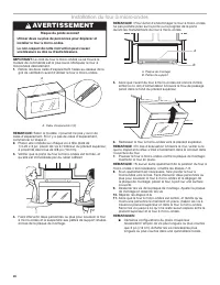
17 Dépose du gabarit de carton Le morceau de carton du dessus de l’emballage du four à microondes est perforé. La partie à l’intérieur de la perforation est à utiliser comme gabarit de mur arrière et comme gabarit d’armoire supérieure. 1. Découper le long des trous perforés pour détacher le gabarit ...
Page 18 - INSTRUCTIONS DE LIAISON; AVERTISSEMENT; Risque de choc électrique
18 Dimensions du produit *La profondeur totale du produit varie légèrement selon la conception de la porte. Spécifi cations électriques Observer les dispositions de tous les codes et règlements en vigueur. Nécessaire : ■ Une alimentation électrique de 120 V, 60 Hz, CAseulement, 15 ou 20 A, protégée ...
Page 19 - INSTRUCTIONS D’INSTALLATION; Dépose de la plaque de montage; Réorientation du moteur du ventilateur
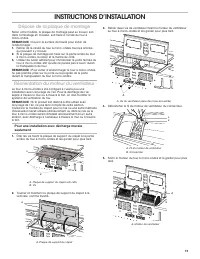
19 INSTRUCTIONS D’INSTALLATION Dépose de la plaque de montage Selon votre modèle, la plaque de montage peut se trouver soit dans l’emballage en mousse, soit fi xée à l’arrièe du four àmicro-ondes. REMARQUE : Couvrir la surface de travail pour éviter de l’endommager. 1. Retirer de la cavité du four à...
Page 23 - Tracé sur le mur arrière
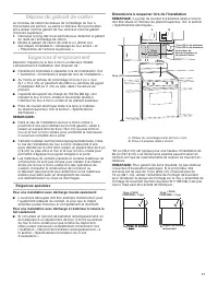
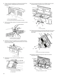
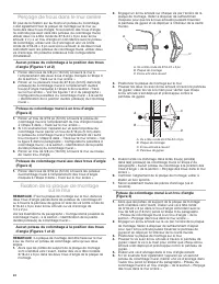
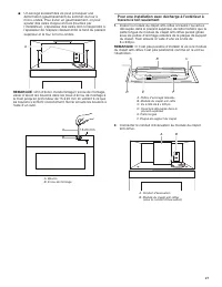
23 Tracé sur le mur arrière Le four à micro-ondes doit être fi xé sur au moins un poteau d colombage mural, et de préférence sur deux poteaux; on utilise pour cela au moins une vis d’ancrage, et de préférence deux vis. 1. Utiliser un mètre ruban; déterminer et marquer clairement la position de l’axe...
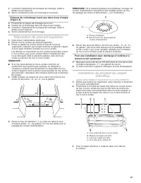
Page 25 - Préparation du placard supérieur; Installation du module du clapet; (pour décharge à travers le mur uniquement)
25 7. Contrôler l’alignement de la plaque de montage; veiller à établir un bon aplomb. 8. Serrer solidement la/les vis d’ancrage et le boulon. Poteaux du colombage mural aux deux trous d’angle (Figure 4) 1. Positionner la plaque de montage sur le mur. 2. Insérer les vis d’ancrage dans les deux trous...
Page 26 - Installation du four à micro-ondes; Risque du poids excessif
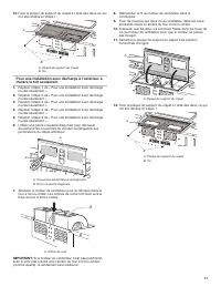
26 Installation du four à micro-ondes IMPORTANT: Le côté du four à micro-ondes où se trouve le module de commande est le plus lourd. Manipuler le four à microondes délicatement. 1. Retirer les deux cales d’espacement fi xées au-dessus de la grill de ventilation avant d'utiliser le four à micro-ondes...
Page 28 - SPÉCIFICATIONS/CONCEPTION DU CIRCUIT D’ÉVACUATION; Achever l’installation
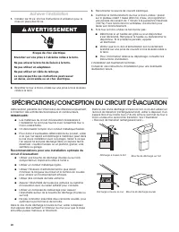
28 SPÉCIFICATIONS/CONCEPTION DU CIRCUIT D’ÉVACUATION Cette section présente de l’information de référence uniquement, à l’intention des architectes/concepteurs et constructeurs. REMARQUES : ■ Les matériaux du circuit d’évacuation nécessaires à l’installation ne sont pas fournis avec l’ensemble four ...
Page 29 - Raccord de transition rectangulaire/rond; Raccords standard recommandés
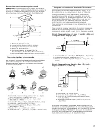
29 Raccord de transition rectangulaire/rond REMARQUE : On doit disposer d’un espace libre de 3 po (7,6 cm) ou plus entre le sommet du four à micro-ondes et le raccord de transition rectangulaire/rond pour que le clapet anti-refl ux puiss manoeuvrer librement et complètement. Raccords standard recomm...
Page 30 - Pièces de rechange; Accessoires
30 ASSISTANCE Appeler le marchand local autorisé ou le centre de service agréé. Lors de l’appel, vous aurez besoin des numéros de modèle et de série du four à micro-ondes. Les deux numéros peuvent être trouvés sur la plaque signalétique située derrière la porte du four à micro-ondes, sur le châssis ...
Page 31 - Remarques