Amana AMV2307PFW - Manual
Amana AMV2307PFW Microwave – Manual, read for free online in PDF format. We hope this helps you resolve any issues you may have. If you have further questions, please contact us through the contact form.
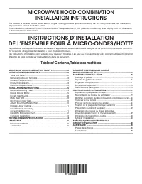


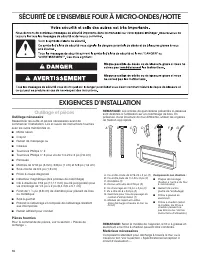
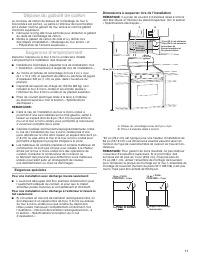
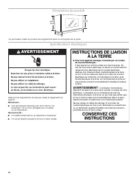
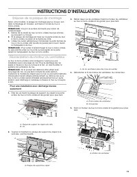
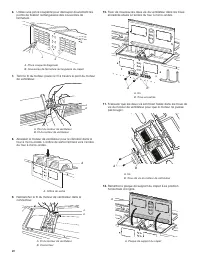
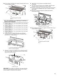
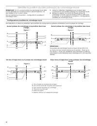
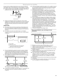
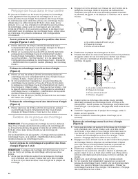
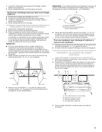
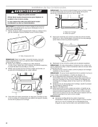
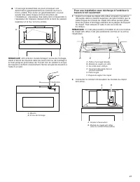
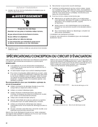
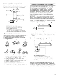
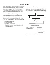


Table of Contents:
- Page 2 – Tools and Parts; Tools Needed
- Page 3 – Special Requirements; For Wall Venting Installation Only:; Installation Dimensions; Product Dimensions
- Page 4 – Electrical Requirements; GROUNDING INSTRUCTIONS; WARNING
- Page 5 – INSTALLATION INSTRUCTIONS; Remove Mounting Plate; Wall Venting Installation Only
- Page 7 – Roof Venting Installation Only
- Page 8 – Possible Wall Stud Confi gurations; Figure 1
- Page 9 – Mark Rear Wall
- Page 10 – Drill Holes in Rear Wall; Installation for Wall Stud at One End Hole (Figure 3); Attach Mounting Plate to Wall; No Wall Studs at End Holes (Figures 1 and 2)
- Page 11 – Prepare Upper Cabinet; For Roof Venting Installation Only:; Install Damper Assembly
- Page 12 – Install the Microwave Oven; Excessive Weight Hazard
- Page 13 – For Roof Venting Installation Only; Complete Installation; Electrical Shock Hazard
- Page 14 – VENTING DESIGN SPECIFICATIONS; For optimal venting installation, we recommend:; Recommended Standard Fittings
- Page 15 – Recommended Vent Length; total; ASSISTANCE; Replacement Parts; Accessories
- Page 16 – Outillage et pièces; Outillage nécessaire; Matériaux nécessaires
- Page 17 – Exigences spéciales; Pour une installation avec décharge murale seulement:; Dimensions à respecter lors de l’installation
- Page 18 – INSTRUCTIONS DE LIAISON; AVERTISSEMENT; Risque de choc électrique
- Page 19 – INSTRUCTIONS D’INSTALLATION; Dépose de la plaque de montage; Réorientation du moteur du ventilateur
- Page 23 – Tracé sur le mur arrière
- Page 25 – Préparation du placard supérieur; Installation du module du clapet; (pour décharge à travers le mur uniquement)
- Page 26 – Installation du four à micro-ondes; Risque du poids excessif
- Page 28 – SPÉCIFICATIONS/CONCEPTION DU CIRCUIT D’ÉVACUATION; Achever l’installation
- Page 29 – Raccord de transition rectangulaire/rond; Raccords standard recommandés
- Page 30 – Pièces de rechange; Accessoires
- Page 31 – Remarques
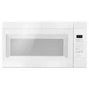
MICROWAVE HOOD COMBINATION
INSTALLATION INSTRUCTIONS
This product is suitable for use above electric or gas cooking products up to and including 36" (91.4 cm) wide. See the “Installation
Requirements” section for further notes.
These installation instructions cover different models. The appearance of your particular model may differ slightly from the illustration
in these installation instructions.
INSTRUCTIONS D’INSTALLATION
DE L’ENSEMBLE FOUR À MICRO-ONDES/HOTTE
Ce produit est conçu pour l’utilisation au-dessus d’appareils de cuisson électriques ou à gaz de 36 po (91,4 cm) de largeur ou moins.
Voir la section « Exigences d’installation » pour d’autres remarques.
Ces instructions d’installation sont valables pour plusieurs modèles. Il se peut que l’apparence de votre propre modèle soit légèrement
différente de celle montrée sur les illustrations dans ce document.
Table of Contents/Table des matières
W11485888B
MICROWAVE HOOD COMBINATION SAFETY ............................2
INSTALLATION REQUIREMENTS .................................................2
Tools and Parts .............................................................................2
Remove Cardboard Template ......................................................3
Location Requirements ................................................................3
Product Dimensions .....................................................................3
Electrical Requirements ...............................................................4
INSTALLATION INSTRUCTIONS ...................................................5
Remove Mounting Plate ...............................................................5
Rotate Blower Motor ....................................................................5
Locate Wall Stud(s) ......................................................................8
Mark Rear Wall .............................................................................9
Drill Holes in Rear Wall ...............................................................10
Attach Mounting Plate to Wall ...................................................10
Prepare Upper Cabinet ..............................................................11
Install Damper Assembly
(for wall venting only) ..................................................................11
Install the Microwave Oven ........................................................12
Complete Installation .................................................................13
VENTING DESIGN SPECIFICATIONS ........................................14
ASSISTANCE ................................................................................15
Replacement Parts .....................................................................15
Accessories ................................................................................15
SÉCURITÉ DE L’ENSEMBLE FOUR À
MICRO-ONDES/HOTTE...............................................................16
EXIGENCES D’INSTALLATION ...................................................16
Outillage et pièces ......................................................................16
Dépose du gabarit de carton .....................................................17
Exigences d’emplacement .........................................................17
Dimensions du produit ...............................................................18
Spécifi cations électriques ..........................................................18
INSTRUCTIONS D’INSTALLATION .............................................19
Dépose de la plaque de montage ..............................................19
Réorientation du moteur du ventilateur .....................................19
Identifi er la position du/des poteau(x) du colombage mural .....22
Tracé sur le mur arrière ..............................................................23
Perçage de trous dans le mur arrière .........................................24
Fixation de la plaque de montage sur le mur ............................24
Préparation du placard supérieur ..............................................25
Installation du module du clapet anti-refl ux
(pour décharge à travers le mur uniquement) ............................25
Installation du four à micro-ondes .............................................26
Achever l’installation ..................................................................28
SPÉCIFICATIONS/CONCEPTION DU
CIRCUIT D’ÉVACUATION ...........................................................28
ASSISTANCE ................................................................................30
Pièces de rechange ....................................................................30
Accessoires ................................................................................30
"Loading the manual" means you need to wait until the file loads and becomes available for online reading. Some manuals are very large, and the time they take to appear depends on your internet speed.
Other Manuals for Amana AMV2307PFW
Summary
2 MICROWAVE HOOD COMBINATION SAFETY INSTALLATION REQUIREMENTS Tools and Parts Tools Needed Gather the required tools and parts before starting installation. Read and follow the instructions provided with any tools listed here. ■ Measuring tape ■ Pencil ■ Masking tape or thumbtacks ■ Scissors ■ No. 2...
3 Remove Cardboard Template The cardboard piece from the top of the microwave oven packaging is perforated. The piece inside the perforation is for use as a rear wall template and upper cabinet template. 1. Cut along the perforation to separate the template from the rest of the cardboard packaging. ...
4 Electrical Requirements Observe all governing codes and ordinances. Required: ■ A 120 V, 60 Hz, AC only, 15 or 20 A electrical supply with a fuse or circuit breaker Recommended: ■ A time-delay fuse or time-delay circuit breaker ■ A separate circuit serving only this microwave oven GROUNDING INSTRU...