Alpine PXI-H990 - Manuals
Alpine PXI-H990 Car Radio – Manual in PDF format online.
Manuals:
Manual Alpine PXI-H990


Summary
2 -EN GUIDE FOR INSTALLATION AND CONNECTIONS • Please read this GUIDE FOR INSTALLATION AND CONNECTIONS and the OWNER’S MANUAL thoroughly to familiarize yourself with each control and function. We at ALPINE hopethat your new PXI-H990 will give you many years of listening enjoyment.In case of problems...
3 -EN DO NOT DAMAGE PIPE OR WIRING WHEN DRILLING HOLES. When drilling holes in the chassis for installation, take precautions so as not to contact, damage or obstruct pipes, fuellines, tanks or electrical wiring. Failure to take such precautions may result in fire. DO NOT USE BOLTS OR NUTS IN THE BR...
4 -EN Precautions • Be sure to disconnect the cable from the (–) battery post before installing your PXI-H990. This will reduce any chance of damage to the unit in case of a short-circuit. • Be sure to connect the color coded leads according to the diagram. Incorrect connections may cause the unit t...
Alpine Car Radios Manuals
-
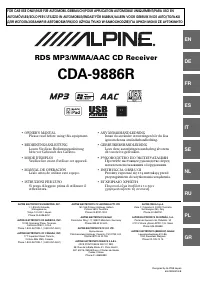 Alpine CDA-9886R
Manual
Alpine CDA-9886R
Manual
-
 Alpine CDE-103BT
Manual
Alpine CDE-103BT
Manual
-
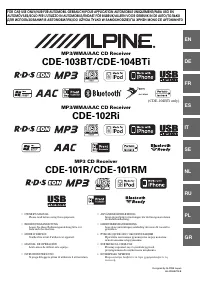 Alpine CDE-104BTi
Manual
Alpine CDE-104BTi
Manual
-
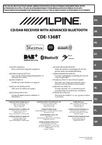 Alpine CDE-136BT
Manual
Alpine CDE-136BT
Manual
-
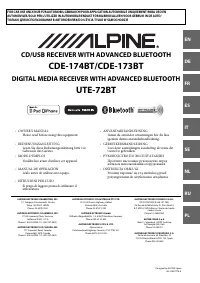 Alpine CDE-173BT
Manual
Alpine CDE-173BT
Manual
-
 Alpine CDE-175R
Manual
Alpine CDE-175R
Manual
-
 Alpine CDE-177BT
Manual
Alpine CDE-177BT
Manual
-
 Alpine CDE-178BT
Manual
Alpine CDE-178BT
Manual
-
 Alpine CDE-183BT
Manual
Alpine CDE-183BT
Manual
-
 Alpine CDE-185BT
Manual
Alpine CDE-185BT
Manual
-
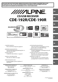 Alpine CDE-190R
Manual
Alpine CDE-190R
Manual
-
 Alpine CDE-192R
Manual
Alpine CDE-192R
Manual
-
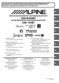 Alpine CDE-195BT
Manual
Alpine CDE-195BT
Manual
-
 Alpine CDE-9880R
Manual
Alpine CDE-9880R
Manual
-
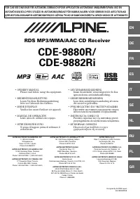 Alpine CDE-9882Ri
Manual
Alpine CDE-9882Ri
Manual
-
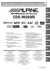 Alpine CDE-W203Ri
Manual
Alpine CDE-W203Ri
Manual
-
 Alpine CDE-W296BT
Manual
Alpine CDE-W296BT
Manual
-
 Alpine HDS-990
User Manual
Alpine HDS-990
User Manual
-
 Alpine ICS-X8
Manual
Alpine ICS-X8
Manual
-
 Alpine iDA-X100M
Manual
Alpine iDA-X100M
Manual