Page 2 - ENGLISH; TABLE OF CONTENTS; COPYRIGHT NOTICE; Dansons; Customer Care
ENGLISH 2 TABLE OF CONTENTS Parts & Specs ...................................................................... 3Assembly Preparation ...................................................... 4Assembly Instructions Mounting The Support Legs To Main Cabinet ....................... 4 Securing The Co...
Page 3 - PB; PB – ELECTRIC REQUIREMENTS
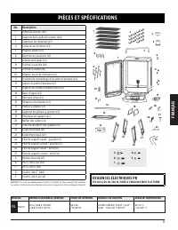
ENGLISH 3 PARTS & SPECS MODEL UNIT ASSEMBLCD (WXHXD) UNIT WEIGHT COOKING AREA TEMPERATURE RANGE PB PBV7P1 734 X 1,468 X 709 MM / 28.8 X 57.8 X 27.9 IN 64.3 KG / 141.09 LB CUBIC COOKING: 0.16 M³ / 5.6 FT³ TOTAL - 11,715 CM² / 1,815 SQ. IN. 65-215°C / 150-420°F Part# Description 1 Cooking Grids (x...
Page 4 - ASSEMBLY INSTRUCTIONS; MOUNTING THE SUPPORT LEGS TO MAIN CABINET; IMPORTANT: The four support legs must be arranged correctly to be; ASSEMBLY PREPARATION; Tools required for assembly:
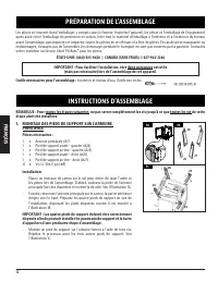
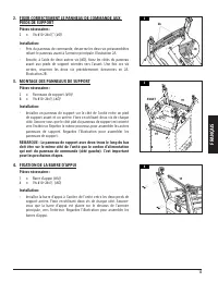
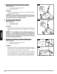
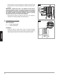
ENGLISH 4 ASSEMBLY INSTRUCTIONS IMPORTANT: It is advised to read each step entirely before starting assembly on instructions. Do not tighten screws completely until all screws for that step have been installed, or unless otherwise mentioned. 1. MOUNTING THE SUPPORT LEGS TO MAIN CABINET Parts Require...
Page 5 - SECURING THE CONTROL BOARD TO SUPPORT LEGS; NOTE: The support panel with two holes along the bottom should; SECURING THE SUPPORT BAR; IMPORTANT: Ensure there is a good seal to the main cabinet, as grease
ENGLISH 5 2 2A 2B 2. SECURING THE CONTROL BOARD TO SUPPORT LEGS Parts Required: 2 x #10–24x½" Screw ( #D) Installation: • Near the Control Board, loosen the two screws connecting the front panel to the main cabinet. Note 2A. • Next, using another two screws, secure the front panel sides to the f...
Page 6 - ATTACHING THE HEAT SHIELD; from the grease exhaust tube may cause damage to the control board.; MOUNTING THE POWER CORD BRACKET; NOTE: The diveted end of the brackets should face the control board.
ENGLISH 6 6. ATTACHING THE HEAT SHIELD Parts Required: 1 x Heat Shield (#22) 2 x #10–24x½" Screw ( #D) Installation: • Position the heat shield between the control board and the grease exhaust tube. Secure using a screw on each side. IMPORTANT: If this part is not installed correctly, the heat a...
Page 7 - PLACING THE GREASE TRAY
ENGLISH 7 10 9. PLACING THE GREASE TRAY Parts Required: 1 x Grease Tray (#17) Installation: • Slide the grease tray into the grease tray brackets on the front underside of the main cabinet, under the control board. NOTE: The grease tray is completely inserted once the front of the tray is pushed in ...
Page 8 - INSTALLING THE COOKING COMPONENTS; IMPORTANT: Fine tune and test the cabinet door latches and hooks to
ENGLISH 8 15. INSTALLING THE COOKING COMPONENTS Parts Required: 14 x Cooking Grid Support Brackets (#2) 6 x Cooking Grids (#1) 1 x Water Pan (#15) 1 x Flame Tamer (#16) Installation: • Insert six cooking grid support brackets into the holes along the left side wall of the interior main cabinet. Once...
Page 9 - CONNECTING TO A POWER SOURCE; STANDARD OUTLET
ENGLISH 9 17. CONNECTING TO A POWER SOURCE NOTE: Before plugging your unit into any electrical outlet, ensure the temperature dial is in the OFF position. Disconnect when not in use. • STANDARD OUTLET This unit requires 110-120 volt, 60 Hz, 250 W service. It must be a 3-prong grounded plug. Ensure g...
Page 10 - FRANÇAIS; TABLE DES MATIÈRES; AVIS SUR LES DROITS D’AUTEUR; Service client
FRANÇAIS 10 TABLE DES MATIÈRES Pièces et spécifications .................................................. 11Préparation de l’assemblage .........................................12Instructions d’assemblage Montage des pieds de support sur l'armoire principale ...........................................
Page 11 - PIÈCES ET SPÉCIFICATIONS; EXIGENCES ÉLECTRIQUES PB
FRANÇAIS 11 PIÈCES ET SPÉCIFICATIONS MODÈLE APPAREIL ASSEMBLÉE (WXHXD) POIDS DE APPAREIL SURFACE DE CUISSON PLAGE DE TEMPÉRATURE PB PBV7P1 734 X 1 468 X 709 MM / 28,8 X 57,8 X 27,9 PO 64,3 KG / 141,09 LB CUISINE CUBIQUE: 0,16 M 3 / 5,6 PI 3 TOTAL - 11,715 CM² / 1,815 PO 2 65-215 °C / 150-420 °F No. ...
Page 12 - PRÉPARATION DE L’ASSEMBLAGE; Outils nécessaires pour l’assemblage :; INSTRUCTIONS D’ASSEMBLAGE; étape aient été installées.; MONTAGE DES PIEDS DE SUPPORT SUR L'ARMOIRE; IMPORTANT : Les quatre pieds de support doivent être correctement
FRANÇAIS 12 PRÉPARATION DE L’ASSEMBLAGE Les pièces se trouvent dans l’emballage, y compris sous le fumeur. Inspectez l'appareil, les pièces et l'emballage de l'équipement après avoir retiré l'emballage de protection en carton. Jeter tout le matériel d'emballage à l'intérieur et à l'extérieur du fume...
Page 13 - FIXER CORRECTEMENT LE PANNEAU DE COMMANDE AUX; REMARQUE : Le panneau de support avec deux trous le long du bas
FRANÇAIS 13 2. FIXER CORRECTEMENT LE PANNEAU DE COMMANDE AUX PIEDS DE SUPPORT Pièces nécessaires : 2 x Vis #10–24x½" ( #D) Installation: • Près du panneau de commande, desserrez les deux vis préassemblées reliant le panneau avant à l'armoire principale. Illustration 2A. • Ensuite, à l'aide de de...
Page 14 - MONTAGE DU TUBE D'ÉVACUATION DES GRAISSES
FRANÇAIS 14 5. MONTAGE DU TUBE D'ÉVACUATION DES GRAISSES Pièces nécessaires : 1 x Tube d'évacuation des graisses (#21) 2 x Vis #10–24x⅓ po ( #E) Installation: • Montez le tube d'évacuation des graisses sur le dessous de l'armoire principale à l'aide de deux vis. IMPORTANT : Assurez-vous que l'armoir...
Page 15 - FIXER LES SUPPORTS DU PLATEAU À GRAISSE
FRANÇAIS 15 8. FIXER LES SUPPORTS DU PLATEAU À GRAISSE Pièces nécessaires : 1 x Boîtier des câbles (#20) 2 x Supports du plateau à graisse (#18) 6 x Vis #10–24x½ po ( #D) Installation: • Tout d'abord, montez le boîtier des câbles sur la base du boîtier de la vis sans fin en utilisant deux vis dans c...
Page 16 - MONTAGE DE LA POIGNÉE ARRIÈRE; SÉCURISATION DE LA CHEMINÉE; REMARQUE : Ajustez le capuchon de la cheminée afin d'affecter le; MONTAGE DU BOUCHON DU COUVERCLE; Installation
FRANÇAIS 16 11. MONTAGE DE LA POIGNÉE ARRIÈRE Pièces nécessaires : 1 x Poignée arrière (#5) 4 x Vis ¼–20x⅝ (#C) Installation : • Montez la poignée arrière au dos de la trémie en utilisant quatre vis. Voir l'illustration. 12. SÉCURISATION DE LA CHEMINÉE Pièces nécessaires : 1 x Capuchon de cheminée (...
Page 17 - FIXATION DE LA POIGNÉE ET DES LOQUETS DE; scelle correctement quand elle est fermée. Un mauvais alignement; INSTALLATION DES COMPOSANTS DE CUISSON; IMPORTANT : Les fenêtres d'aération sur les côtés du boîtier du
FRANÇAIS 17 14. FIXATION DE LA POIGNÉE ET DES LOQUETS DE LA PORTE D'ARMOIRE Pièces nécessaires : 1 x Poignée de porte d’armoire (#10) 2 x Crochets de verrouillage de la porte d'armoire (#11) 2 x Loquet de porte d'armoire (#12) 10 x Vis #10–24x½ (#D) Installation : • Tout d'abord, réinstallez la port...
Page 18 - des aliments pendant une période prolongée, mettez le réservoir; UTILISATION DES CROCHETS
FRANÇAIS 18 • Ensuite, insérez le réservoir d'eau dans les supports de grille les plus bas à l'intérieur de l'armoire. Remplissez le réservoir d'eau aux ¾ avec de l'eau. IMPORTANT : Assurez-vous qu'il y ait toujours de l'eau dans le réservoir pendant la cuisson. Il va récupérer la graisse et les gou...
Page 19 - CONNECTION À UNE SOURCE D'ALIMENTATION; REMARQUE : Avant de brancher votre unité dans une prise électrique,; PRISE STANDARD
FRANÇAIS 19 17. CONNECTION À UNE SOURCE D'ALIMENTATION REMARQUE : Avant de brancher votre unité dans une prise électrique, assurez-vous que la molette de température est en position SMOKE. Débranchez le câble quand l'appareil n'est pas utilisé. • PRISE STANDARD Cette unité nécessite un voltage de 11...
Page 20 - NE RETOURNEZ PAS LE PRODUIT AU MAGASIN; IMPORTANT; DO NOT RETURN PRODUCT TO STORE
WARNING: This product can expose you to chemicals including wood dust, which is known to the state of California to cause cancer. Combustion of this product can expose you to chemicals including carbon monoxide, which is known to the state of California to cause birth defects or other reproductive h...