Page 4 - CONTENTS
4 CONTENTS 1. IMPORTANT INFORMATION ........................................................................................................................... 5 1.1 Symbols and Their Meanings ..............................................................................................................
Page 5 - Symbols and Their Meanings; Warning; Disposing of the packing materials; IMPORTANT INFORMATION
5 EN 1.1 Symbols and Their Meanings Symbols used in the installation manual are as follows. NoteImportant information or useful tips for use Warning Conditions that may damage the product or affect its operation Caution Situations entailing a serious risk of injury 1.2 Disposing of the packing mater...
Page 6 - Food Load Bearing Capacity of the Doors
6 1.3 Climate class Climate range Ambient temperature of the room This appliance has been designed to be used in certain specific climates (ambient temperatures ranges). It must not be used outside of these ranges. SN (Extended temperate) Between +50ºF (10ºC) and +90ºF (32ºC) N (Temperate) Between +...
Page 7 - Installation location; You must follow the instructions below:; BEFORE INSTALLATION
7 EN 2.1 Installation location You must follow the instructions below: > The floor on which the product is to be installed must be capable of bearing 1,200 pounds (544 kg) minimum. > The kitchen floor and the bottom of the product must be equally level. Otherwise, problems may occur with the a...
Page 8 - Electrical Connection; > The electrical outlet must be grounded and
8 2.2 Cabinetry Make sure that the cabinetry inside which you will install the appliance has been securely mounted in your kitchen. Your cabinet must be properly secured to the floor and to the wall using appropriate mounting hardware. For the best installation, clearances between the cabinet and th...
Page 10 - Location of the Electrical Wiring
10 2.9 Location of the Electrical Wiring The location of the electrical outlet in the cabinet where the product is to be installed must be within the area shown in the figure. CAUTION: Do not use extension cords or two-prong adapters and do not remove the ground terminal of the grounding cable. CAUT...
Page 11 - Location of the Water System; • The level of the floor where the product
11 EN 2.10 Location of the Water System The water connected to the water supply must be potable.The location of the water line connection must be within the area shown in the figure below.The refrigerator's water system must be connected to the house's main water supply. The user must be able to swi...
Page 12 - Product dimensions
12 2. BEFORE INSTALLATION 2.11 Product dimensions Category REF18FCBIPRV / REF18FCBIPLV REF24FCBIPNV REF24RCBPNV REF30RCBPNV A 17 3/4" (451mm) 23 3/4" (603mm) 23 3/4" (603mm) 29 3/4” (756mm) without panel: 23 5/16” (592 mm) with panel: 24 ¼” (616 mm)
Page 13 - Wall
13 EN Category REF18FCBIPRV / REF18FCBIPLV REF24FCBIPNV REF24RCBPNV REF30RCBPNV A 20” (508) 26” (660) 26” (660) 32” (813) B 4 3/8” (110) 4 3/8” (110) 4 3/8” (110) 4 3/8” (110) C 11” (280) 14” (356) 14” (356) 16” (406) A : Door depth (90°) B : Minimum door clearance to adjacent wall ( 90°- reduced in...
Page 18 - Removing the Connectors on the Side Wall of the Unit; Conference
18 2.13 Removing the Connectors on the Side Wall of the Unit No. Part name Specs 18 24 30 1 Trim furniture top PVC extrusion L=457 1 PVC extrusion L=609 1 PVC extrusion L=762 1 2 Trim furniture side PVC extrusion L=1,259 2 2 2 PVC extrusion L=617 2 2 2 3 Trim door side PVC extrusion L=1,781 2 2 2 Co...
Page 19 - Removing the Installation Hardware
19 EN 2.14 Removing the Installation Hardware No Part name Spec 18 24 30 Remark 1 Anti-tip bracket T4.0, Cr+zn-coating 8 8 8 2 Anti tip bracket screws and dowels M8*L60 8 8 8 3 Position adjustment jig PS 1 1 1 4 Cover furniture door bracket abs - 2 2 5 Truss washer head M4*12 - 2 2 6 Bracket furnitu...
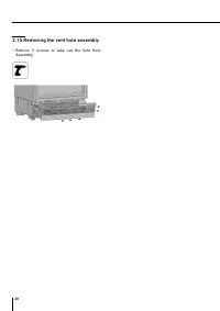
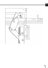
Page 20 - Removing the vent hole assembly; • Remove 5 screws to take out the Vent Hole
20 2.15 Removing the vent hole assembly • Remove 5 screws to take out the Vent Hole Assembly.
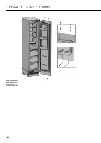
Page 21 - INSTALLATION INSTRUCTIONS; Before Installation; • Use a tape measure to mark the wall for
21 EN 3. INSTALLATION INSTRUCTIONS 3.1 Before Installation Proceed with installation of the product according to the instructions below. Be sure to take into account national and local code requirements regarding installations. Please comply with the following: • For the USA, The National Electrical...
Page 22 - • For the most secure installation, use a stud-finder
22 3. INSTALLATION INSTRUCTIONS • For the most secure installation, use a stud-finder to secure the anti-tip brackets in wall studs. If no studs are present at the correct installation location, follow the instructions below. WARNING: Always make sure that the area to be drilled into is free of any ...
Page 24 - Preparing the Water Hose and the; • Method A: Position the water hose and the power; Installation in the cabinet; • Slowly tilt the refrigerator back and remove it
24 3. INSTALLATION INSTRUCTIONS 3.3 Preparing the Water Hose and the Electrical Connection Inspect all water connections for leaks. Water leaks can cause significant damage over time. It is recommended to use a ¼” water line with a minimum length of 60" (1.5 meters) with a threaded ¼” female con...
Page 26 - • Push the product carefully towards the
26 3. INSTALLATION INSTRUCTIONS WARNING: Make sure that the power cord does not get wedged in when placing the product. • Push the product carefully towards the cabinet to position it; the unit should slide into the niche with relative ease. If you experience resistance while placing the product in ...
Page 28 - • For panel-ready units, the refrigerator should be
28 3. INSTALLATION INSTRUCTIONS • For panel-ready units, the refrigerator should be installed at a depth that takes into consideration the custom overlay panel thickness, so as to ensure a flush installation, if desired. NOTE:It is important to align the upper edge of the freezer drawer when alignin...
Page 30 - • Use 2 wrenches to firmly connect both the hose
30 3. INSTALLATION INSTRUCTIONS INSTALLING THE BOTTOM CABINETComplete the water connection• Use a cutter to cut of any excess waterline length, allowing sufficient slack of 10” (254 mm) to ensure an easy bend and clear connection, with no tension or potential kinks in the supply line that runs to th...
Page 34 - • Remove the two screws to remove the door
34 3. INSTALLATION INSTRUCTIONS REMOVING THE OVERLAY PANEL MECHANISM COVERS• Remove the upper screws to remove the upper cover. REF18FCBIPRV / REF18FCBIPLVREF24FCBIPNVREF24RCBPNV REF30RCBPNV WARNING: There is a magnet on the cover door hanger bracket. This is a functional component for product opera...
Page 35 - REF18FCBIPRV / REF18FCBIPLV
35 EN REMOVING THE PANEL BRACKETS• Remove the upper and lower adjustable panel mounting brackets from the door panel adjustment mechanisms, as shown below. REF18FCBIPRV / REF18FCBIPLV REF24FCBIPNVREF24RCBPNVREF30RCBPNV
Page 36 - PREPARING THE OVERLAY PANELS
36 3. INSTALLATION INSTRUCTIONS PREPARING THE OVERLAY PANELS NOTE:When marking, you can use the door/drawer panel preparation template provided with the product. REF18FCBIPRV / REF18FCBIPLV REF24FCBIPNVREF24RCBPNVREF30RCBPNV WARNING: The handle mounting holes will have to be adjusted based on the ha...
Page 39 - • Use the bracket furniture door(Item No6) to join
39 EN ALIGNING THE LOWER PART OF THE CUSTOM DOOR PANEL WITH BOLTS. Up&Down Front & back Fixing furniture door completely • Use the bracket furniture door(Item No6) to join the furniture door • Use 2screws (Item No7) and 1screw(Item No5) to fix. REF24FCBIPNVREF24RCBPNV REF30RCBPNV
Page 40 - • Clip the cover furniture door bracket.
40 3. INSTALLATION INSTRUCTIONS • Clip the cover furniture door bracket. REF24FCBIPNVREF24RCBPNV REF30RCBPNV • Attach and screw the upper/lower decoration cover. REF18FCBIPRV / REF18FCBIPLV
Page 42 - • After the top and bottom door panel brackets are
42 • After the top and bottom door panel brackets are secured by installing screws, use screw(Item No8) and square washer(Item No9) to secure the center mounting bracket. • Attach the Trim door side (Item No3) Tape double
Page 43 - ADJUSTING THE SPRING TENSION OF THE HINGES; • Use a drill to adjust the tension of the upper and
43 EN 3.6 Hinge Adjustment and Reversing the Door Swing ADJUSTING THE SPRING TENSION OF THE HINGES • Use a drill to adjust the tension of the upper and lower hinges of the fridge door. Set the hinge adjustment screw to position "I" from position "O". WARNING: The door must be fully o...
Page 44 - • Loosen the 2 screws in the upper cover of the
44 3. INSTALLATION INSTRUCTIONS • Loosen the 2 screws in the upper cover of the fridge door and remove it. • Take out the upper adjustment kits. REF18FCBIPRV / REF18FCBIPLV REF24FCBIPNVREF24RCBPNV REF30RCBPNV
Page 48 - • Take off the fridge door and lay it on a table top,
48 3. INSTALLATION INSTRUCTIONS REMOVING AND PREPARING THE INNER DOOR• Remove the hinge connection screws from the hinge brackets. CAUTION:The door will be released when these screws are removed. You must take measures to prevent the door from falling.You can tape the cabinet door to the inner door ...
Page 50 - • Air vent upper part for the right hinge; • Air vent upper part for the left hinge
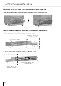
50 AIR VENT UPPER PART DIRECTION CHANGE • Remove the air vent part and change direction as shown in the figure. HOW TO CHANGE AIR VENT UPPER PART DIRECTION • Air vent upper part for the right hinge Air vent cover Air vent hinge part right • Air vent upper part for the left hinge Air vent hinge part ...
Page 52 - REINSTALLING THE DOOR; • Place the inner door on the refrigerator using
52 REINSTALLING THE DOOR • Place the inner door on the refrigerator using the door seal to help hold the door in place and fasten it back onto the hinges using 4 screws. 3. INSTALLATION INSTRUCTIONS
Page 53 - SIDE BY SIDE CONFIGURATION INSTALLATION; • All freezer columns include one connection trim kit (CTXV).
53 EN SIDE BY SIDE CONFIGURATION INSTALLATION • All freezer columns include one connection trim kit (CTXV). CABINET CUTOUT DIMENSIONSPlease check cabinet cutout dimensions below before starting the installation. Configuration 18+24 18+30 24+24 24+30 30+30 “A” Dimension 42” (1066mm) 48” (1219mm) 48” ...
Page 54 - LOCATION OF THE ELECTRICAL WIRING
54 LOCATION OF THE ELECTRICAL WIRING Location of the electrical wiring must be within the range given below. ATTENTION:Do not use extension cables or two-pin adaptors and do not remove the ground terminal of the grounding cable. ATTENTION:A qualified electrician must ensure that the poles of the soc...
Page 55 - LOCATION OF THE WATER SYSTEM
55 EN LOCATION OF THE WATER SYSTEM The water connected to the water mains must be potable.Location of the water system must be within the range given below.Water system of the refrigerator must be connected to the water mains system in the house.The user must be able to switch it on/off with the val...
Page 57 - INSTALLING THE UPPER AND LOWER BRACKETS; • Once aligned, use screws to attach the Upper
57 EN INSTALLING THE UPPER AND LOWER BRACKETS Install the Upper and Lower Brackets, as per the pictures below: Upper brackets Lower bracket Attach the Insulating Foil centered to the side of one of the refrigerator units, as per the picture below: • Position the two refrigerators side-by-side, ensur...
Page 58 - LEVELING THE REFRIGERATORS; • Using a drill and the bit shown below, engage
58 • Connect the power supply to the refrigerators.• Install the water connections for the refrigerators, following the manufacturer’s instructions. • Gently push the refrigerators into their final position, making sure they are level and stable. LEVELING THE REFRIGERATORS • Using a drill and the bi...
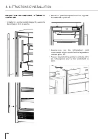
Page 60 - INSTALLING THE LATERAL AND UPPER TRIMS; • Install the lateral trims onto the right and left
60 INSTALLING THE LATERAL AND UPPER TRIMS • Install the lateral trims onto the right and left connection brackets. • Install the upper trim onto the upper connection brackets. • Ensure that the refrigerators are properly aligned before inserting the Center Trim (part #5). • Gently push the Center Tr...
Page 64 - CONTENIDO
64 CONTENIDO 1. INFORMACIÓN IMPORTANTE ....................................................................................................................... 65 1.1 Símbolos y sus significados .............................................................................................................
Page 65 - INFORMACIÓN IMPORTANTE
65 ES 1.1 Símbolos y sus significados Los símbolos utilizados en el manual de instalación son los siguientes. NotaInformación importante o consejos útiles para su uso Advertencia Condiciones que pueden dañar el producto o afectar a su funcionamiento Precaución Situaciones que entrañen un riesgo grav...
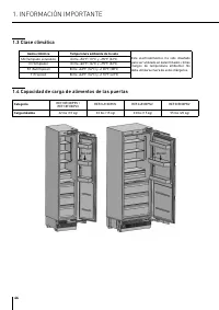
Page 66 - Capacidad de carga de alimentos de las puertas
66 1.3 Clase climática Gama climática Temperatura ambiente de la sala Este electrodoméstico ha sido diseñado para ser utilizado en determinados climas (rangos de temperatura ambiente). No debe utilizarse fuera de estos márgenes. SN (Templado extendido) Entre +50ºF (10ºC) y +90ºF (32ºC) N (Templado) ...
Page 67 - Lugar de instalación; debe comprobarse con un nivel de burbuja.; ANTES DE LA INSTALACIÓN
67 ES 2.1 Lugar de instalación Debe seguir las siguientes instrucciones:> El suelo sobre el que se va a instalar el producto debe ser capaz de soportar 544 kg (1.200 libras) como mínimo. > El suelo de la cocina y la parte inferior del producto deben estar igualmente nivelados. De lo contrario,...
Page 68 - Conexión eléctrica; > La toma de corriente debe estar conectada a tierra; Lista de herramientas
68 2.2 Armarios Asegúrese de que los armarios dentro de los cuales va a instalar el electrodoméstico han sido montados de forma segura en su cocina. Su armario debe fijarse correctamente al suelo y a la pared utilizando los herrajes de montaje adecuados. Para una instalación óptima, las distancias e...
Page 70 - Ubicación del cableado eléctrico
70 2.9 Ubicación del cableado eléctrico La ubicación de la toma de corriente en el armario donde se vaya a instalar el producto debe estar dentro de la zona indicada en la figura. PRECAUCIÓN: No utilice alargadores ni adaptadores de dos clavijas y no retire el terminal de tierra del cable de conexió...
Page 71 - Ubicación del sistema de agua
71 ES 2.10 Ubicación del sistema de agua El agua conectada al suministro de agua debe ser potable. La ubicación de la conexión de la línea de agua debe estar dentro del área que se muestra en la figura siguiente. El sistema de agua del refrigerador debe estar conectado al suministro principal de agu...
Page 72 - Dimensiones del producto
72 2. ANTES DE LA INSTALACIÓN 2.11 Dimensiones del producto Categoría REF18FCBIPRV / REF18FCBIPLV REF24FCBIPNV REF24RCBPNV REF30RCBPNV A 17 3/4" (451 mm) 23 3/4" (603 mm) 23 3/4" (603 mm) 29 3/4" (756 mm) sin panel: 23 5/16" (592 mm) con panel: 24 ¼" (616 mm)
Page 73 - Pared
73 ES Categoría REF18FCBIPRV / REF18FCBIPLV REF24FCBIPNV REF24RCBPNV REF30RCBPNV A 20" (508) 26" (660) 26" (660) 32" (813) B 4 3/8" (110) 4 3/8" (110) 4 3/8" (110) 4 3/8" (110) C 11" (280) 14" (356) 14" (356) 16" (406) A : Profundidad de la puerta (90°...
Page 78 - Extracción de los conectores de la pared lateral de la unidad
78 2.13 Extracción de los conectores de la pared lateral de la unidad N.º Nombre de pieza Espec. 18 24 30 1 Recorte la parte superior del mueble Extrusión de PVC L=457 1 Extrusión de PVC L=609 1 Extrusión de PVC L=762 1 2 Recorte el lado del mueble Extrusión de PVC L=1.259 2 2 2 Extrusión de PVC L=6...
Page 79 - Extracción de los herrajes de instalación
79 ES 2.14 Extracción de los herrajes de instalación N.º Nombre de pieza Espec. 18 24 30 Observación 1 Soporte antivuelco ,Revestimiento de Cr+Zn T4.0 8 8 8 2 Tornillos y espigas del soporte antivuelco M8*L60 8 8 8 3 Posición de la plantilla de ajuste PS 1 1 1 4 Soporte de puerta para muebles de cub...
Page 80 - • Retire 5 tornillos para sacar el conjunto del
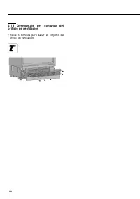
80 2.15 Desmontaje del conjunto del orificio de ventilación • Retire 5 tornillos para sacar el conjunto del orificio de ventilación.
Page 81 - INSTRUCCIONES DE INSTALACIÓN; Antes de la instalación; • Para Canadá, el Código Eléctrico Canadiense,; Montaje de los soportes antivuelco; • Utilice una cinta métrica para marcar la pared
81 ES 3. INSTRUCCIONES DE INSTALACIÓN 3.1 Antes de la instalación Proceda a la instalación del producto según las instrucciones siguientes. Asegúrese de tener en cuenta los requisitos de los códigos nacionales y locales relativos a las instalaciones. Por favor, cumpla con lo siguiente: • Para EE.UU....
Page 84 - Preparación de la manguera de; Instalación en el armario
84 3. INSTRUCCIONES DE INSTALACIÓN 3.3 Preparación de la manguera de agua y la conexión eléctrica Inspeccione todas las conexiones de agua en busca de fugas. Las fugas de agua pueden causar daños importantes con el tiempo. Se recomienda utilizar una línea de agua de ¼ pulg. (6,35 mm) con una longitu...
Page 85 - Colocación del refrigerador en el hueco del armario.
85 ES NOTA: Extreme las precauciones al manipular la unidad, ya que la parte inferior del refrigerador tiene componentes vitales para su correcto funcionamiento; si se dañan estos componentes, podría producirse una avería o una posible fuga de condensado y daños en el suelo. PRECAUCIÓN: El riesgo de...
Page 86 - • Empuje el producto con cuidado hacia el
86 3. INSTRUCCIONES DE INSTALACIÓN ADVERTENCIA:Asegúrese de que el cable de alimentación no quede encajado al colocar el producto. • Empuje el producto con cuidado hacia el armario para colocarlo; la unidad debería deslizarse en el hueco con relativa facilidad. Si experimenta resistencia al colocar ...
Page 87 - • Para los productos con puertas de paneles de
87 ES • Después de regular las patas ajustables, compruebe que el electrodoméstico está nivelado tanto de lado a lado como de atrás hacia delante colocando un nivel en el suelo del compartimento del congelador (para ello deberá retirar el estante). Ajuste del refrigerador en función del hueco del ar...
Page 88 - • Para las unidades preparadas para paneles, el
88 3. INSTRUCCIONES DE INSTALACIÓN • Para las unidades preparadas para paneles, el refrigerador debe instalarse a una profundidad que tenga en cuenta el grosor del panel superpuesto a medida, con el fin de garantizar una instalación enrasada, si así se desea. NOTA:Es importante alinear el borde supe...
Page 90 - • Utilice 2 llaves para conectar firmemente tanto
90 3. INSTRUCCIONES DE INSTALACIÓN INSTALACIÓN DEL ARMARIO INFERIORComplete la conexión de agua• Utilice un cúter para cortar cualquier exceso de longitud de la línea de agua, dejando una holgura suficiente de 10 pulg. (254 mm) para garantizar un doblado fácil y una conexión clara, sin tensiones ni ...
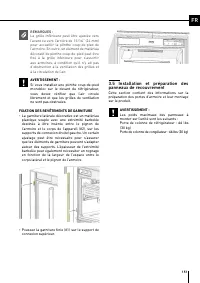
Page 91 - soporte de conexión superior.; Instalación y preparación del panel
91 ES NOTA:La rejilla inferior puede ajustarse hacia delante o hacia atrás 15/16 pulg. (24 mm) para acomodar el rodapié del armario. Además, se puede colocar un trozo de material decorativo para los pies de los armarios en la rejilla inferior para que haga juego con los armarios, siempre que no obst...
Page 94 - • Retire los dos tornillos para quitar el soporte
94 3. INSTRUCCIONES DE INSTALACIÓN RETIRADA DE LAS CUBIERTAS DEL MECANISMO DEL PANEL SUPERPUESTO• Retire los tornillos superiores para quitar la cubierta superior. REF18FCBIPRV / REF18FCBIPLVREF24FCBIPNVREF24RCBPNV REF30RCBPNV ADVERTENCIA:Hay un imán en el soporte para colgar la puerta de cubierta. ...
Page 96 - PREPARACIÓN DE LOS PANELES SUPERPUESTOS
96 3. INSTRUCCIONES DE INSTALACIÓN PREPARACIÓN DE LOS PANELES SUPERPUESTOS NOTA:A la hora de marcar, puede utilizar la plantilla de preparación del panel de la puerta/cajón que se suministra con el producto. REF18FCBIPRV / REF18FCBIPLV REF24FCBIPNVREF24RCBPNVREF30RCBPNV ADVERTENCIA: Los orificios de...
Page 99 - • Utilice el soporte para puerta de mueble (pieza
99 ES ALINEACIÓN DE LA PARTE INFERIOR DEL PANEL DE PUERTA A MEDIDA CON PERNOS. Arriba y abajo Delante y detrás Fijación completa de la puerta del mueble • Utilice el soporte para puerta de mueble (pieza n.º 6) para unir la puerta de mueble • Utilice 2 tornillos (pieza n.º 7) y 1 tornillo (pieza n.º ...
Page 100 - • Enganche el soporte de puerta del mueble de la
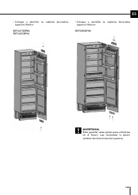
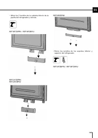
100 3. INSTRUCCIONES DE INSTALACIÓN • Enganche el soporte de puerta del mueble de la cubierta. REF24FCBIPNVREF24RCBPNV REF30RCBPNV • Coloque y atornille la cubierta decorativa superior/inferior. REF18FCBIPRV / REF18FCBIPLV
Page 103 - • Utilice un taladro para ajustar la tensión de las
103 ES 3.6 Ajuste de las bisagras e inversión del giro de la puerta AJUSTE DE LA TENSIÓN DEL MUELLE DE LAS BISAGRAS • Utilice un taladro para ajustar la tensión de las bisagras superior e inferior de la puerta del refrigerador. Coloque el tornillo de ajuste de la bisagra en la posición «I» desde la ...
Page 104 - • Afloje los 2 tornillos de la cubierta superior de la
104 3. INSTRUCCIONES DE INSTALACIÓN • Afloje los 2 tornillos de la cubierta superior de la puerta del refrigerador y retírela. • Retire los kits de ajuste superior. REF18FCBIPRV / REF18FCBIPLV REF24FCBIPNVREF24RCBPNV REF30RCBPNV
Page 108 - • Retire la puerta del refrigerador y colóquela
108 3. INSTRUCCIONES DE INSTALACIÓN DESMONTAJE Y PREPARACIÓN DE LA PUERTA INTERIOR• Retire los tornillos de conexión de los soportes de las bisagras. PRECAUCIÓN:La puerta se soltará cuando se retiren estos tornillos. Debe tomar medidas para evitar que la puerta se caiga.Puede encintar la puerta del ...
Page 112 - REINSTALACIÓN DE LA PUERTA; • Coloque la puerta interior en el refrigerador
112 REINSTALACIÓN DE LA PUERTA • Coloque la puerta interior en el refrigerador utilizando la junta de la puerta para ayudar a mantenerla en su sitio y fíjela de nuevo en las bisagras utilizando 4 tornillos. 3. INSTRUCCIONES DE INSTALACIÓN
Page 113 - INSTALACIÓN CON CONFIGURACIÓN LADO A LADO
113 ES INSTALACIÓN CON CONFIGURACIÓN LADO A LADO • Todas las columnas de congelación incluyen un kit de embellecedor de conexión (CTXV). DIMENSIONES DEL RECORTE DEL ARMARIOCompruebe las dimensiones del recorte del armario, a continuación, antes de comenzar la instalación. Configuración 18+24 18+30 2...
Page 114 - UBICACIÓN DEL CABLEADO ELÉCTRICO
114 UBICACIÓN DEL CABLEADO ELÉCTRICO La ubicación del cableado eléctrico debe estar dentro de los márgenes indicados a continuación. ATENCIÓN:No utilice cables alargadores ni adaptadores de dos clavijas y no retire el terminal de tierra del cable de conexión a tierra. ATENCIÓN:Un electricista cualif...
Page 115 - UBICACIÓN DEL SISTEMA DE AGUA
115 ES UBICACIÓN DEL SISTEMA DE AGUA El agua conectada a la red debe ser potable.La ubicación del sistema de agua debe estar dentro de los márgenes indicados a continuación.El sistema de agua del refrigerador debe estar conectado a la red de agua doméstica.El usuario debe poder encenderlo/apagarlo c...
Page 117 - • Coloque los dos refrigeradores uno al lado del
117 ES INSTALACIÓN DE LOS SOPORTES SUPERIOR E INFERIOR Instale los soportes superior e inferior, según las imágenes a continuación: Soportes superiores Soporte inferior Fije la lámina aislante centrada en el lateral de una de las unidades del refrigerador, tal y como se muestra en la imagen inferior...
Page 118 - • Empuje suavemente los refrigeradores hasta; NIVELACIÓN DE LOS REFRIGERADORES; • Utilizando un taladro y la broca que se muestra
118 • Conecte la fuente de alimentación a los refrigeradores. • Instale las conexiones de agua para los refrigeradores, siguiendo las instrucciones del fabricante. • Empuje suavemente los refrigeradores hasta su posición final, asegurándose de que estén nivelados y estables. NIVELACIÓN DE LOS REFRIG...
Page 124 - SOMMAIRE
124 SOMMAIRE 1. INFORMATIONS IMPORTANTES ................................................................................................................. 125 1.1 Symboles et signification ..................................................................................................................
Page 125 - INFORMATIONS IMPORTANTES
125 FR 1.1 Symboles et signification Les symboles utilisés dans le manuel d’installation sont les suivants. RemarqueInformations importantes ou conseils utiles pour l’utilisation Avertissement Conditions susceptibles d’endommager le produit ou de nuire à son fonctionnement Mise en garde Situations c...
Page 126 - Classe climatique; Capacité de chargement des portes du réfrigérateur
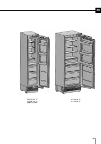
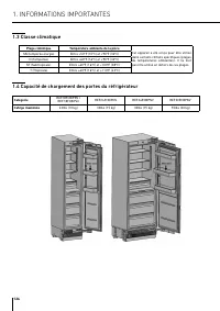
126 1.3 Classe climatique Plage climatique Température ambiante de la pièce Cet appareil a été conçu pour être utilisé dans certains climats spécifiques (plages de températures ambiantes). Il ne doit pas être utilisé en dehors de ces plages. SN (tempérée élargie) Entre +50ºF (10ºC) et +90ºF (32ºC) N...
Page 127 - Lieu d’installation; AVANT D’INSTALLER L’APPAREIL
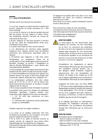
127 FR 2.1 Lieu d’installation Veuillez suivre les instructions suivantes : > Le sol sur lequel le produit doit être installé doit pouvoir supporter un poids minimum de 1 200 livres (544 kg). > Le sol de la cuisine et le bas du produit doivent être de niveau l’un par rapport à l’autre. Sinon, ...
Page 128 - Raccordement électrique; > La prise électrique doit être mise à la terre et; Raccordement à la ligne; > La pression de la ligne d’alimentation en eau doit; Liste de l’outillage
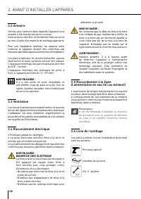
128 2.2 Armoire Vérifiez que l’armoire dans laquelle l’appareil sera installé a été montée de façon correcte. Votre armoire doit être correctement fixée au sol et au mur à l’aide d’un matériel de montage approprié. Pour une installation optimale, les espaces entre l’armoire et l’appareil doivent êtr...
Page 130 - Emplacement du câblage électrique
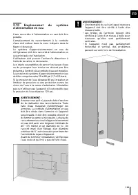
130 2.9 Emplacement du câblage électrique L’emplacement de la prise électrique dans l’armoire où le produit sera installé doit se situer dans la zone indiquée sur la figure. MISE EN GARDE : N’utilisez pas de rallonges ou d’adaptateurs à deux broches, et ne retirez pas la borne de terre du câble de m...
Page 132 - Dimensions de l’appareil
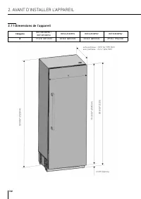
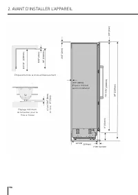
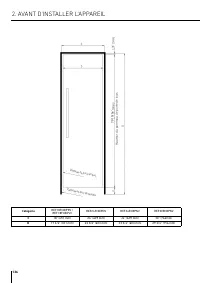
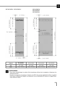
132 2. AVANT D’INSTALLER L’APPAREIL 2.11 Dimensions de l’appareil Catégorie REF18FCBIPRV / REF18FCBIPLV REF24FCBIPNV REF24RCBPNV REF30RCBPNV A 17 3/4" (451 mm) 23 3/4" (603 mm) 23 3/4" (603 mm) 29 3/4” (756 mm) sans panneau : 23 5/16” (592 mm) avec panneau : 24 ¼” (616 mm)
Page 133 - Paroi
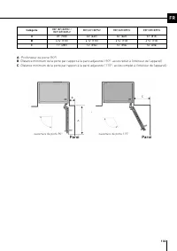
133 FR Catégorie REF18FCBIPRV / REF18FCBIPLV REF24FCBIPNV REF24RCBPNV REF30RCBPNV A 20” (508) 26” (660) 26” (660) 32” (813) B 4 3/8” (110) 4 3/8” (110) 4 3/8” (110) 4 3/8” (110) C 11” (280) 14” (356) 14” (356) 16” (406) A : Profondeur de porte (90°) B : Distance minimum de la porte par rapport à la ...
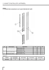
Page 138 - Retrait des connecteurs sur la paroi latérale de l’unité
138 2.13 Retrait des connecteurs sur la paroi latérale de l’unité N° Nom de la pièce Spécifications 18 24 30 1 Garniture meuble supérieure Extrusion de PVC L=457 1 Extrusion de PVC L=609 1 Extrusion de PVC L=762 1 2 Garniture meuble latérale Extrusion de PVC L=1 259 2 2 2 Extrusion de PVC L=617 2 2 ...
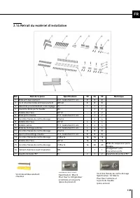
Page 139 - Retrait du matériel d’installation
139 FR 2.14 Retrait du matériel d’installation Non Nom de la pièce Spécifications 18 24 30 Remarque 1 Bride anti-basculement T4.0, revêtement Cr+zn- 8 8 8 2 Vis et chevilles bride anti basculement M8*L60 8 8 8 3 Gabarit de positionnement et de réglage PS 1 1 1 4 Couvercle bride porte meuble abs - 2 ...
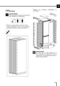
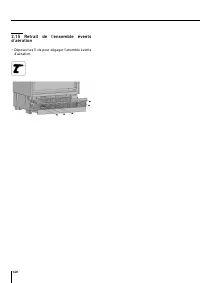
Page 140 - • Déposez les 5 vis pour dégager l’enemble évents
140 2.15 Retrait de l’ensemble évents d’aération • Déposez les 5 vis pour dégager l’enemble évents d’aération.
Page 141 - INSTRUCTIONS D’INSTALLATION; Avant d’installer le produit; • Pour le Canada, le Code canadien de l’électricité,; basculement; • À l’aide d’un ruban à mesurer, marquez les
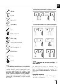
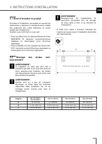
141 FR 3. INSTRUCTIONS D’INSTALLATION 3.1 Avant d’installer le produit Procédez à l’installation du produit en suivant les instructions ci-dessous. Il convient de tenir compte des exigences des codes nationaux et locaux relatifs aux installations. Veuillez vous conformer à ce qui suit : • Pour les É...
Page 142 - • Pour que l’installation soit la plus sûre possible,
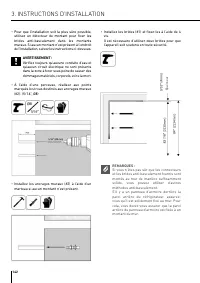
142 3. INSTRUCTIONS D’INSTALLATION • Pour que l’installation soit la plus sûre possible, utilisez un détecteur de montant pour fixer les brides anti-basculement dans les montants muraux. Si aucun montant n’est présent à l’endroit de l’installation, suivez les instructions ci-dessous. AVERTISSEMENT :...
Page 144 - Préparation du tuyau d’eau et du
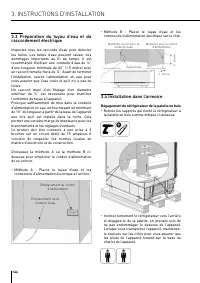
144 3. INSTRUCTIONS D’INSTALLATION 3.3 Préparation du tuyau d’eau et du raccordement électrique Inspectez tous les raccords d’eau pour détecter les fuites. Les fuites d’eau peuvent causer des dommages importants au fil du temps. Il est recommandé d’utiliser une conduite d’eau de ¼’’ d’une longueur m...
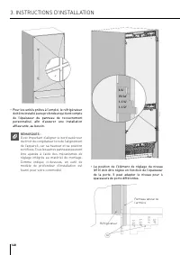
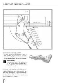
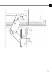
Page 148 - • Pour les unités prêtes à l’emploi, le réfrigérateur
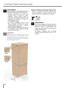
148 3. INSTRUCTIONS D’INSTALLATION • Pour les unités prêtes à l’emploi, le réfrigérateur doit être installé à une profondeur qui tient compte de l’épaisseur du panneau de recouvrement personnalisé, afin d’assurer une installation affleurante, au besoin. REMARQUES :Il est important d’aligner le bord ...
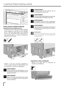
Page 150 - • Utilisez 2 clés pour raccorder fermement à
150 3. INSTRUCTIONS D’INSTALLATION INSTALLATION DE L’ARMOIRE INFÉRIEUREAchèvement du raccordement à l’eau• À l’aide d’un cutter, coupez toute longueur de ligne d’eau excessive, en laissant un mou suffisant de 10’’ (254 mm) pour assurer une courbure facile et un raccordement net, sans tension ni plis...
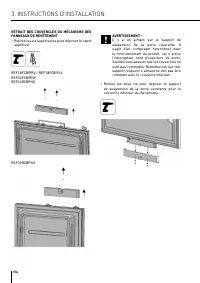
Page 154 - • Retirez les deux vis pour déposer le support
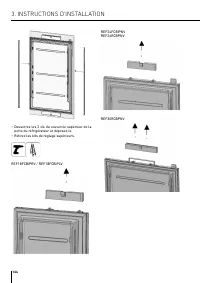
154 3. INSTRUCTIONS D’INSTALLATION RETRAIT DES COUVERCLES DU MÉCANISME DES PANNEAUX DE REVÊTEMENT• Retirez les vis supérieures pour déposer le capot supérieur. REF18FCBIPRV / REF18FCBIPLVREF24FCBIPNVREF24RCBPNV REF30RCBPNV AVERTISSEMENT :Il y a un aimant sur le support de suspension de la porte couv...
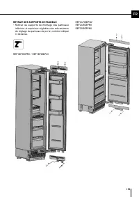
Page 156 - PRÉPARATION DES PANNEAUX DE REVÊTEMENT
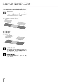
156 3. INSTRUCTIONS D’INSTALLATION PRÉPARATION DES PANNEAUX DE REVÊTEMENT REMARQUES :Lors du marquage, vous pouvez utiliser le gabarit de préparation du panneau de porte/tiroir fourni avec le produit. REF18FCBIPRV / REF18FCBIPLV REF24FCBIPNVREF24RCBPNVREF30RCBPNV AVERTISSEMENT : Les trous de montage...
Page 159 - • Utilisez le support de porte du meuble (article n°
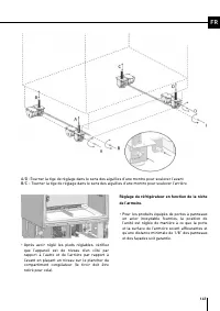
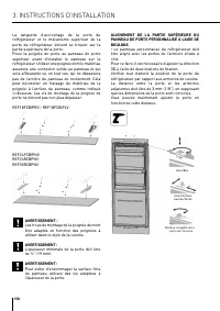
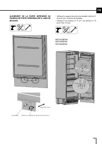
159 FR ALIGNEMENT DE LA PARTIE INFÉRIEURE DU PANNEAU DE PORTE PERSONNALISÉ À L’AIDE DE BOULONS. Haut/Bas Avant/Arrière Fixation complète de la porte de l’armoire • Utilisez le support de porte du meuble (article n° 6) pour unir la porte du meuble. • Utilisez 2 vis (article n° 7) et 1 vis (article n°...
Page 160 - • Clipsez le support de porte du meuble de
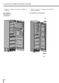
160 3. INSTRUCTIONS D’INSTALLATION • Clipsez le support de porte du meuble de couverture. REF24FCBIPNVREF24RCBPNV REF30RCBPNV • Fixez et vissez le couvercle de décoration supérieur/inférieur. REF18FCBIPRV / REF18FCBIPLV
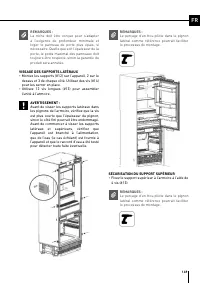
Page 162 - • Une fois que les supports de panneau de porte
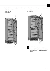
162 • Une fois que les supports de panneau de porte supérieur et inférieur sont fixés à l’aide des vis, utilisez une vis (article n° 8) et une rondelle carrée (article n° 9) pour fixer le support de montage central. • Fixez la garniture côté porte (article n° 3). Ruban adhésif double
Page 163 - RÉGLAGE DE LA TENSION DU RESSORT DES; • Utilisez une perceuse pour ajuster la tension
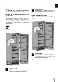
163 FR 3.6 Réglage de la charnière et inversion du sens d’ouverture de la porte RÉGLAGE DE LA TENSION DU RESSORT DES CHARNIÈRES • Utilisez une perceuse pour ajuster la tension des charnières supérieures et inférieures de la porte du réfrigérateur. Placez la vis de réglage de la charnière sur la posi...
Page 164 - • Desserrez les 2 vis du couvercle supérieur de la
164 3. INSTRUCTIONS D’INSTALLATION • Desserrez les 2 vis du couvercle supérieur de la porte du réfrigérateur et déposez-le. • Retirez les kits de réglage supérieurs. REF18FCBIPRV / REF18FCBIPLV REF24FCBIPNVREF24RCBPNV REF30RCBPNV
Page 168 - supports de charnière.
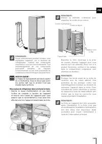
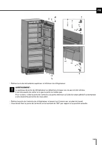
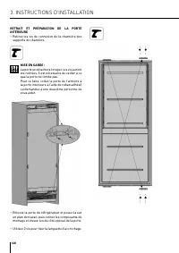
168 3. INSTRUCTIONS D’INSTALLATION RETRAIT ET PRÉPARATION DE LA PORTE INTÉRIEURE• Retirez les vis de connexion de la charnière des supports de charnière. MISE EN GARDE :La porte se détachera lorsque ces vis auront été retirées. Il est nécessaire de veiller à ce que la porte ne tombe pas.Pour ce fair...
Page 169 - l’autre côté où vous fixerez les charnières.
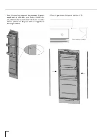
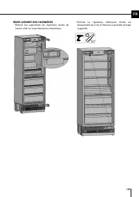
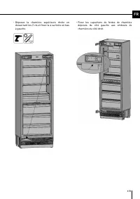
169 FR REMPLACEMENT DES CHARNIÈRES• Retirez les capuchons de charnière situés de l’autre côté où vous fixerez les charnières. • Retirez la charnière inférieure droite en desserrant les 2 vis et fixez-la à sa fente en haut à gauche.
Page 172 - RÉINSTALLATION DE LA PORTE; • Placez la porte intérieure sur le réfrigérateur à
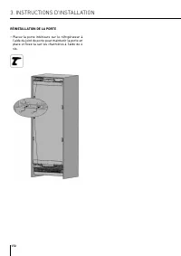
172 RÉINSTALLATION DE LA PORTE • Placez la porte intérieure sur le réfrigérateur à l’aide du joint de porte pour maintenir la porte en place et fixez-la sur les charnières à l’aide de 4 vis. 3. INSTRUCTIONS D’INSTALLATION
Page 173 - INSTALLATION DE LA CONFIGURATION CÔTE À CÔTE
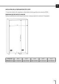
173 FR INSTALLATION DE LA CONFIGURATION CÔTE À CÔTE • Toutes les colonnes de congélateur comprennent un kit de garniture de connexion (CTXV). DIMENSIONS DE DÉCOUPE DE L’ARMOIREVérifiez les dimensions de découpe de l’armoire ci-dessous avant de commencer l’installation. Configuration 18+24 18+30 24+2...
Page 174 - EMPLACEMENT DU CÂBLAGE ÉLECTRIQUE
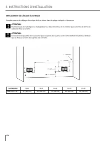
174 EMPLACEMENT DU CÂBLAGE ÉLECTRIQUE L’emplacement du câblage électrique doit se situer dans la plage indiquée ci-dessous. ATTENTION :N’utilisez pas de rallonges ou d’adaptateurs à deux broches, et ne retirez pas la borne de terre du câble de mise à la terre. ATTENTION :Un électricien qualifié doit...
Page 175 - EMPLACEMENT DU SYSTÈME D’ALIMENTATION EN EAU
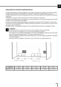
175 FR EMPLACEMENT DU SYSTÈME D’ALIMENTATION EN EAU La ligne d’alimentation en eau du réfrigérateur raccordée au système de conduites d'eau doit être potable.L’emplacement du système d’alimentation en eau doit se situer dans la plage indiquée ci-dessous.La ligne d’alimentation en eau du réfrigérateu...
Page 177 - • Placez les deux réfrigérateurs côte-à-côte en
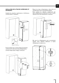
177 FR INSTALLATION DES ATTACHES SUPÉRIEURES ET INFÉRIEURES Installez les attaches supérieures et inférieures comme illustré ci-dessous : Supports supérieurs Supports inférieurs Fixez la plaque avec isolant intégré de manière centrée sur le côté de l’un des réfrigérateurs, comme indiqué dans l’image...
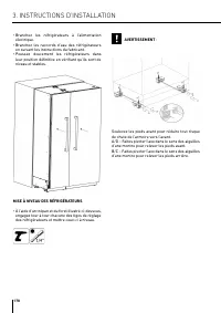
Page 178 - MISE À NIVEAU DES RÉFRIGÉRATEURS; • À l’aide d’un trépan et du foret illustré ci-dessous,
178 • Branchez les réfrigérateurs à l’alimentation électrique. • Branchez les raccords d’eau des réfrigérateurs en suivant les instructions du fabricant. • Poussez doucement les réfrigérateurs dans leur position définitive en vérifiant qu’ils sont de niveau et stables. MISE À NIVEAU DES RÉFRIGÉRATEU...
Page 179 - • Fixez les supports de connexion au réfrigérateur
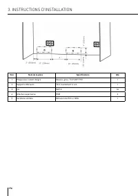
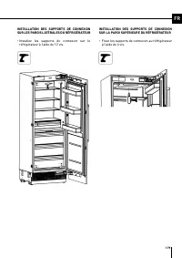
179 FR INSTALLATION DES SUPPORTS DE CONNEXION SUR LES PAROIS LATÉRALES DU RÉFRIGÉRATEUR • Installez les supports de connexion sur le réfrigérateur à l’aide de 12 vis. INSTALLATION DES SUPPORTS DE CONNEXION SUR LA PAROI SUPÉRIEURE DU RÉFRIGÉRATEUR • Fixez les supports de connexion au réfrigérateur à ...