Zoeller 98-0001 - User Manual
Zoeller 98-0001 Pump – User Manual, read for free online in PDF format. We hope this helps you resolve any issues you may have. If you have further questions, please contact us through the contact form.


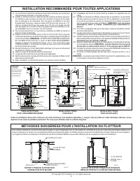
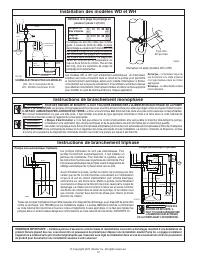
Table of Contents:
- Page 2 – liability in connection with our products.; MANUFACTURER EXPRESSLY DISCLAIMS LIABILITY FOR SPECIAL,; may not apply to you.; Limited Warranty; to find the Authorized Service Station in your area.; SERVICE CHECKLIST
- Page 3 – SUGGESTED METHODS OF FLOAT INSTALLATION; RECOMMENDED INSTALLATION FOR ALL APPLICATIONS; NOTE: THE HOLE MUST ALSO
- Page 4 – WD & WH MODEL INSTALLATION; THREE PHASE WIRING INSTRUCTIONS; NONAUTOMATIC; SINGLE PHASE WIRING INSTRUCTIONS
- Page 5 – AGUAS CLOACALES; Su Tranquilidad es Nuestra Prioridad; FECHA DE INSTALACIÓN:; INSTRUCCIONES DE INSTALACIÓN; MODELOS RECOMENDADOS; VER ABAJO LA LISTA DE ADVERTENCIAS
- Page 6 – EL FABRICANTE EXPRESAMENTE RECHAZA RESPONSABILIDAD POR DAÑOS; GARANTÍA LIMITADA; PRECAUCIONES ELÉCTRICAS -; LISTA DE VERIFICACIÓN DE SERVICIO
- Page 7 – INSTALACIÓN RECOMENDADA PARA TODAS LAS APLICACIONES; En algunas instalaciones es deseable; MÉTODOS SUGERIDOS PARA LA INSTALACIÓN DEL FLOTADOR; SOPORTE COLGANTE PARA FLOTADOR TÍPICO EN FOSOS DE
- Page 8 – INSTRUCCIONES PARA LA INSTALACIÓN DE LOS MODELOS WD Y WH; INSTRUCCIONES PARA EL CABLEADO MONOFÁSICO; INSTRUCCIONES PARA EL CABLEADO TRIFÁSICO; se deben
- Page 9 – FAX; DATE D’INSTALLATION :; INSTRUCTIONS D’INSTALLATION; MODÈLES RECOMMANDÉS; AVERTISSEMENT; ÉGOUT
- Page 10 – LISTE DE VÉRIFICATIONS POUR L’ENTRETIEN; de service agréé le plus proche.; GARANTIE LIMITÉE
- Page 11 – MÉTHODES SUGGÉRÉES POUR L’INSTALLATION DU FLOTTEUR
- Page 12 – AVANT L’INTERVENTION.; « Risque d’électrocution ».; Instructions de branchement monophasé; Définition de la plage de pompage en; Instructions de branchement triphasé; doit; Pompe non-automatique triphasée
1
© Copyright 2011 Zoeller Co. All rights reserved.
INSTALLATION INSTRUCTIONS
RECOMMENDED MODELS
P/N 151797
Notice to installing contractor: Instructions must remain with installation.
SECTION: 6.10.002
FM2676
1011
Supersedes
New
PREINSTALLATION CHECKLIST - ALL INSTALLATIONS
DATE INSTALLED:
MODEL NUMBER:
1. Inspect your pump.
Occasionally, products are damaged during shipment. If the unit is damaged, contact your dealer before using.
DO NOT
remove the test plugs in the cover nor the motor housing.
2. Carefully read the literature
provided to familiarize yourself with specific details regarding installation and use. These materials should be retained for future reference.
NOTICE: VENT HOLE FOR
CHECK V
ALVE
SEE #3 IN CAUTION SECTION
BELOW
AND #4 ON P
AGE 3
EFFLUENT*/SUMP/DEWATERING SEWAGE
49 / 53 / 57 Series, 98 Series
264 Series
137 Series, 151 / 152 / 153 Series
266 / 267 / 268 Series
SEE BELOW FOR
LIST OF CAUTIONS
SEE BELOW FOR
LIST OF WARNINGS
1.
Make certain that the receptacle is within the reach of the pump’s power supply cord. DO NOT
USE AN EXTENSION CORD. Extension cords that are too long or too light do not deliver sufficient
voltage to the pump motor. But, more important, they could present a safety hazard if the insulation
were to become damaged or the connection end were to fall into the sump.
2. Make sure the pump electrical supply circuit is equipped with fuses or circuit breakers of
proper capacity.
A separate branch circuit is recommended, sized according to the “National
Electrical Code” for the current shown on the pump nameplate.
3. Testing for ground.
As a safety measure, each electrical outlet should be checked for ground
using an Underwriters Laboratory Listed circuit analyzer which will indicate if the power, neutral and
ground wires are correctly connected to your outlet. If they are not, call a qualified licensed electrician.
4. For Added Safety.
Pumping and other equipment with a 3-prong grounded plug must be connected
to a 3-prong grounded receptacle. For added safety the receptacle may be protected with a ground-
fault circuit interrupter. When a pump needs to be connected in a watertight junction box, the plug
can be removed and spliced to the supply cable with proper grounding. For added safety this circuit
may be protected by a ground-fault circuit interrupter. The complete installation must comply with
the National Electrical Code and all applicable local codes and ordinances.
5. FOR YOUR PROTECTION, ALWAYS DISCONNECT PUMP FROM ITS POWER SOURCE BEFORE
HANDLING
. Single phase pumps are supplied with a 3-prong grounded plug to help protect you
against the possibility of electrical shock.
DO NOT UNDER ANY CIRCUMSTANCES REMOVE
THE GROUND PIN.
The 3-prong plug
must
be inserted into a mating 3-prong grounded receptacle.
If
the installation does not have such a receptacle, it must be changed to the proper type, wired
and grounded in accordance with the National Electrical Code and all applicable local codes and
ordinances. Three phase pumps require motor starting devices with motor overload protection. See
FM0486 for duplex installations.
6.
The tank is to be vented in accordance with local plumbing code. Pumps
must
be installed in
accordance with the National Electrical Code and all applicable local codes and ordinances. Pumps
are not to be installed in locations classified as hazardous in accordance with National Electrical
Code, ANSI/NFPA 70.
7. “Risk of electrical shock”
Do not remove power supply cord and strain relief or connect conduit
directly to the pump.
8.
Installation and servicing of electrical circuits and hardware should be performed by a qualified
licensed electrician.
9.
Pump installation and servicing should be performed by a qualified person.
10.
Risk of electric shock - These pumps have not been investigated for use in swimming pool and
marine areas.
11.
According to the state of California (Prop 65), this product contains chemicals known to the state
of California to cause cancer and birth defects or other reproductive harm.
1.
Check to be sure your power source is capable of handling the voltage requirements of the motor,
as indicated on the pump name plate.
2.
The installation of automatic pumps with variable level float switches or nonautomatic pumps using
auxiliary variable level float switches is the responsibility of the installing party and care should be
taken that the tethered float switch will not hang up on the pump apparatus or pit peculiarities and
is secured so that the pump will shut off. It is recommended to use rigid piping and fittings and the
pit be 18" or larger in diameter.
3. Information - vent hole purpose.
It is necessary that all submersible sump, effluent, and sewage
pumps capable of handling various sizes of solid waste be of the bottom intake design to reduce
clogging and seal failures. If a check valve is incorporated in the installation, a vent hole (approx.
3/16") must be drilled in the discharge pipe below the check valve and pit cover to purge the unit
of trapped air. Trapped air is caused by agitation and/or a dry basin. Vent hole should be checked
periodically for clogging. The 53 / 57, and 98 Series pumps have a vent located in the pump housing
opposite the float, adjacent to a housing lug, but an additional vent hole is recommended. The vent
hole on a High Head application may cause too much turbulence. You may not want to drill one.
If you choose not to drill a vent hole, be sure the pump case and impeller is covered with liquid
before connecting the pipe to the check valve and no inlet carries air to the pump intake.
NOTE:
THE HOLE MUST ALSO BE BELOW THE BASIN COVER AND CLEANED PERIODICALLY.
Water
stream will be visible from this hole during pump run periods.
4.
Pump should be checked frequently for debris and/or build up which may interfere with the float “on”
or “off” position. Repair and service should be performed by Zoeller Pump Company Authorized
Service Station only.
5.
Dewatering and effluent sump pumps are not designed for use in pits handling raw sewage.
6.
Maximum operating temperature for standard model pumps must not exceed 130°F (54°C).
7.
Pump models 266, 267, 268, and 137 must be operated in an upright position. Do not attempt to
start pump when tilted or laying on its side.
8.
Do not operate a pump in an application where the Total Dynamic Head is less than the minimum
Total Dynamic Head listed on the Pump Performance Curves.
REFER TO WARRANTY ON PAGE 2.
NOTE: Pumps with the “UL” mark and pumps with the “US” mark are tested to UL Standard UL778.
CSA Certified pumps are certified to CSA Standard C22.2 No. 108.
Product information presented
here reflects conditions at time
of publication. Consult factory
regarding discrepancies or
inconsistencies.
MAIL TO: P.O. BOX 16347 • Louisville, KY 40256-0347
SHIP TO: 3649 Cane Run Road • Louisville, KY 40211-1961
(502) 778-2731 • 1 (800) 928-PUMP • FAX (502) 774-3624
visit our web site:
www.zoeller.com
®
Your Peace of Mind is Our Top Priority
®
"Loading the manual" means you need to wait until the file loads and becomes available for online reading. Some manuals are very large, and the time they take to appear depends on your internet speed.
Was this manual helpful?
About this manual
- Brand
- Zoeller
- Model
- 98-0001
- Document type
- User Manual
- Category
- Pump
- Language(s)
- English, Spanish, French
- Pages
- 12
- File size
- 2.3 MB
- Format
Summary
2 © Copyright 2011 Zoeller Co. All rights reserved. we do not authorize any representative or other person to assume for us any other liability in connection with our products. Contact Manufacturer at, 3649 Cane Run Road, Louisville, Kentucky 40211, Attention: Customer Service Department to obtain a...
3 © Copyright 2011 Zoeller Co. All rights reserved. On some installations it may be desirable to install an independent hanger for the level control switches to avoid possible hang ups on the pumps, piping, valves, etc. Float hangers are available from Zoeller Company on Catalog Sheet FM0526 or can ...
4 © Copyright 2011 Zoeller Co. All rights reserved. WD & WH MODEL INSTALLATION WIRING DIAGRAM FOR MODELS WD - 230V, 1 Ph, 60 Hz. WH - 200/208V, 1 Ph, 60 Hz. Models WD & WH are fully automatic. A float switch is included and factory wired in the pump circuit to provide automatic operation onc...