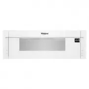
Whirlpool WML55011HW - Installation Manual
Whirlpool WML55011HW Microwave – Installation Manual, read for free online in PDF format. We hope this helps you resolve any issues you may have. If you have further questions, please contact us through the contact form.


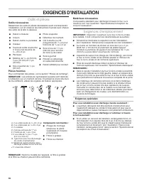
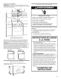
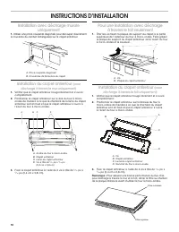
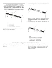
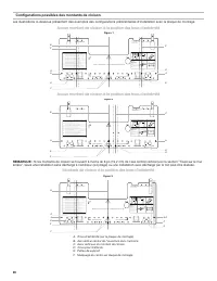
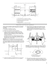
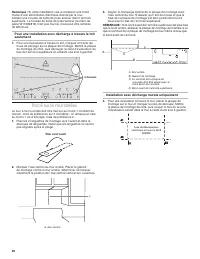
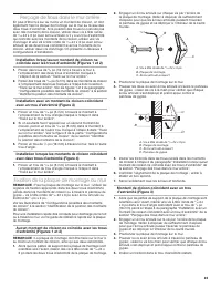
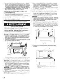
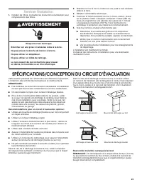
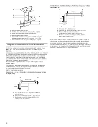
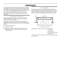

Table of Contents:
- Page 2 – INSTALLATION REQUIREMENTS; Tools and Parts; Tools needed; Location Requirements; Special Requirements; For Wall Venting Installation Only:
- Page 3 – Installation Dimensions; Product Dimensions; A B; Electrical Shock Hazard; WARNING; GROUNDING INSTRUCTIONS; For all cord connected appliances:
- Page 4 – INSTALLATION INSTRUCTIONS
- Page 5 – Vent Cover Installation; (for both upper vent and wall vent installation)
- Page 6 – Possible Wall Stud Configurations; No Wall Studs at End Holes; installation can be done.; Wall Studs at End Holes
- Page 7 – Prepare Upper Cabinet
- Page 8 – Roof Venting Installation Only; Mark Rear Wall; Wall Venting Installation Only
- Page 9 – Drill Holes in Rear Wall; Installation for No Wall Studs at End Holes (Figures 1; Attach Mounting Plate to Wall; No Wall Studs at End Holes (Figures 1 and 2)
- Page 10 – Install the Microwave Oven; Excessive Weight Hazard; A B
- Page 11 – Complete Installation; VENTING DESIGN SPECIFICATIONS; For optimal venting installation, we recommend:
- Page 12 – Recommended Vent Length; See the following examples.
- Page 13 – ASSISTANCE; Replacement Parts
- Page 14 – NOTE
- Page 15 – INSTRUCTIONS D’UTILISATION DE L’ENSEMBLE; Table des matières; SÉCURITÉ DE L’ENSEMBLE HOTTE/FOUR À MICRO-ONDES; Risque possible de décès ou de blessure grave si vous ne; Votre sécurité et celle des autres est très importante.; AVERTISSEMENT; présentes dans ces instructions d’installation.
- Page 16 – EXIGENCES D’INSTALLATION; Outils et pièces; Outils nécessaires; Exigences d’emplacement; Exigences spéciales; Pour une installation avec décharge murale seulement :
- Page 17 – Dimensions d’installation; Dimensions du produit; Risque de choc électrique; INSTRUCTIONS DE LIAISON; Pour tout appareil ménager connecté par un cordon; L’utilisation incorrecte du
- Page 18 – INSTRUCTIONS D’INSTALLATION
- Page 19 – Installation du couvercle d’évent; (pour décharge à travers le mur et à l’extérieur); Identification de la position des montants de cloison
- Page 20 – Configurations possibles des montants de cloison; Aucun montant de cloison à la position des trous d’extrémité
- Page 21 – Montants de cloison à la position des trous d’extrémité; Préparation de l’armoire supérieure
- Page 22 – Tracé sur le mur arrière; Installation avec décharge murale uniquement
- Page 24 – Montant de cloison coïncident avec deux trous; Installation du four à micro-ondes; Risque du poids excessif
- Page 25 – Terminer l’installation; SPÉCIFICATIONS/CONCEPTION DU CIRCUIT D’ÉVACUATION; Recommandations pour un circuit d’évacuation optimal :
- Page 26 – Longueur recommandée du circuit d’évacuation; Conduit de 3 1⁄
- Page 27 – Pièces de rechange
- Page 28 – REMARQUE
MICROWAVE HOOD COMBINATION
INSTALLATION INSTRUCTIONS
Table of Contents
MICROWAVE HOOD COMBINATION SAFETY
You can be killed or seriously injured if you don't immediately
You
can be killed or seriously injured if you don't follow
All safety messages will tell you what the potential hazard is, tell you how to reduce the chance of injury, and tell you what can
happen if the instructions are not followed.
Your safety and the safety of others are very important.
We have provided many important safety messages in this manual and on your appliance. Always read and obey all safety
messages.
This is the safety alert symbol.
This symbol alerts you to potential hazards that can kill or hurt you and others.
All safety messages will follow the safety alert symbol and either the word “DANGER” or “WARNING.”
These words mean:
follow instructions.
instructions.
DANGER
WARNING
MICROWAVE HOOD COMBINATION SAFETY ............................1
INSTALLATION REQUIREMENTS .................................................2
Tools and Parts .............................................................................2
Location Requirements ................................................................2
Product Dimensions .....................................................................3
Electrical Requirements .............................................................3
INSTALLATION INSTRUCTIONS ...................................................4
Wall Venting Installation Only .......................................................4
Install Damper Assembly (for wall venting only) ..........................4
Roof Venting Installation Only ......................................................4
Install Damper Assembly (for roof venting only) ..........................4
Vent Cover Installation .................................................................5
Locate Wall Stud(s) ......................................................................5
Prepare Upper Cabinet ................................................................7
Mark Rear Wall .............................................................................8
Drill Holes in Rear Wall .................................................................9
Attach Mounting Plate to Wall .....................................................9
Install the Microwave Oven ........................................................10
Complete Installation .................................................................11
VENTING DESIGN SPECIFICATIONS .........................................11
ASSISTANCE ................................................................................13
This product is suitable for use above electric or gas cooking products up to and including 36" (91.4 cm) wide. See the “Installation
Requirements” section for further notes.
These installation instructions cover different models. The appearance of your particular model may differ slightly from the illustration
in these installation instructions.
W11209522C
"Loading the manual" means you need to wait until the file loads and becomes available for online reading. Some manuals are very large, and the time they take to appear depends on your internet speed.
Was this manual helpful?
About this manual
- Brand
- Whirlpool
- Model
- WML55011HW
- Document type
- Installation Manual
- Category
- Microwave
- Language(s)
- English, French
- Pages
- 28
- File size
- 4 MB
- Format
Other Manuals for Whirlpool WML55011HW
Summary
2 INSTALLATION REQUIREMENTS Tools and Parts Tools needed Gather the required tools and parts before starting installation. Read and follow the instructions provided with any tools listed here. ■ Measuring tape ■ Pencil ■ Masking tape or thumbtacks ■ Scissors ■ No. 3 Phillips screwdriver for ¼- 20 x ...
3 Installation Dimensions NOTE: The grounded 3 prong outlet must be inside the upper cabinet. See the “Electrical Requirements” section. *24” (61 cm) is typical for 60” (152.4 cm) installation height. Exact dimensions may vary depending on type of range/ cooktop below. NOTE: To ensure good performan...
4 Wall Venting Installation Only 1. Using diagonal wire cutting pliers, gently snip out the rectangular vent cover on the damper plate. Install Damper Assembly (for wall venting only) 1. Check that damper blade moves freely, and opens fully. 2. Position the damper assembly on the back of the microwa...
Ask a question
Related manuals
Popular Whirlpool Microwaves
More Whirlpool Microwaves models
 Whirlpool WMH78019HZ User Manual
 Whirlpool WMH78519LV User Manual
 Whirlpool WMH78519LZ Installation Manual
 Whirlpool WML55011HB Installation Manual
 Whirlpool WML55011HS User Manual
 Whirlpool WML75011HZ User Manual
 Whirlpool WMMF5930PV Manual
 Whirlpool WMMF5930PZ Installation Manual
 Whirlpool WMMF7330RZ User Manual
 Whirlpool WMT50011KS Installation Manual
 Whirlpool WMT55511KS User Manual
 Whirlpool AMW 848 Manual