Page 2 - CONTENTS; WELCOME 3; To purchase accessories for your tool, visit
2 CONTENTS WELCOME 3 Specifications ................................................................................................... 3Introduction ..................................................................................................... 4 SAFETY 5 Safety Information .....................
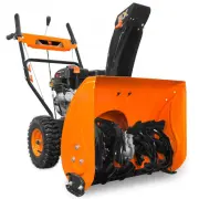
Page 3 - SPECIFICATIONS; ENGINE
SPECIFICATIONS Model Number SB24E Stages 2-Stage Maximum Clearing Width 24 inches Maximum Clearing Height 21 inches Tire Size 13 x 4.10 - 6 Recommended Tire Pressure 20 - 24 PSI (137.9 - 165 kPa) Wheel Valve Type Schrader Speeds 4 Forward, 2 Reverse Chute Range of Motion 190 degrees Weight 172 lbs P...
Page 4 - INTRODUCTION; SERVICE RECORD
4 INTRODUCTION Thanks for purchasing the WEN snow blower. Refer to the illustration below for the location of the serial number on the side of the gas tank. Record the snow blower information in the spaces provided below. If assistance for information or service is required, please contact customer ...
Page 5 - SAFETY INFORMATION; SAFETY INTRODUCTION; safety for both yourself and others.; SAFETY SYMBOLS
5 SAFETY INFORMATION WARNING: Before operating the snow blower, make sure to read all safety warnings and all instructions. Failure to follow the warnings and instructions may result in electric shock, fire or serious injury. SAFETY INTRODUCTION Safety is a combination of common sense, staying alert...
Page 6 - SNOW BLOWER SAFETY WARNINGS
6 SNOW BLOWER SAFETY WARNINGS DANGER: CARBON MONOXIDE Using a snow blower indoors CAN KILL YOU IN MINUTES . Snow blower exhaust contains carbon monoxide (CO). This is a poison gas you cannot see or smell. If you can smell the snow blower exhaust, you are breathing CO. But even if you cannot smell th...
Page 7 - OPERATING ENVIRONMENT
7 SNOW BLOWER SAFETY WARNINGS OPERATING ENVIRONMENT 1. Using a snow blower indoors can kill you in min- utes. Only use a snow blower outside and far away from windows, doors and vents. 2. Do not smoke near the snow blower. 3. Do not operate near open flame, heat, or flamma- ble materials. This snow ...
Page 8 - SNOW BLOWER OPERATION
8 9 5. If using the electric start function, ensure the ex- tension cord is of the proper gauge. Refer to the exten- sion cord chart on p. 9 for the recommended gauge and length of extension cord. 6. Disengage all control levers before starting the en- gine. 7. Do not make any adjustments to the mac...
Page 9 - ELECTRICAL INFORMATION; AMPERAGE; GUIDELINES AND RECOMMENDATIONS FOR EXTENSION CORDS; Examine extension cord before use.; UNPACKING; UNPACKING & TRANSPORTATION
8 99 ELECTRICAL INFORMATION AMPERAGE REQUIRED GAUGE FOR EXTENSION CORDS 25 ft. 50 ft. 100 ft. 150 ft. 11A 16 gauge 16 gauge 14 gauge 12 gauge GUIDELINES AND RECOMMENDATIONS FOR EXTENSION CORDS When using an extension cord, be sure to use one heavy enough to carry the current your product will draw. ...
Page 10 - PACKING LIST
10 PACKING LIST UNPACKING & TRANSPORTATION Pre-Assembled Chute Components Shift Lever Components Tools Chute Rotator Components Spare Parts Upper Handle Assembly (1) Lower Handle Assembly (1) Flat Cotter Pin (4 total - 2 spare) 8mm Washer (2) 10mm Washer (1) Rotator Seat (1) Screwdriver (1) Open...
Page 11 - User Controls Close-Up; KNOW YOUR SNOW BLOWER; TOOL PURPOSE
User Controls Close-Up KNOW YOUR SNOW BLOWER 11 TOOL PURPOSE Snow blowers allow you to clear snow quickly and efficiently. Refer to the following diagrams to become familiar- ized with all the parts and controls of your snow blower. The components will be referred to later in the manual for assembly...
Page 12 - ASSEMBLY & ADJUSTMENTS
12 ASSEMBLY & ADJUSTMENTS INSTALLING THE LOWER HANDLE (FIG. 1) 1. Remove the four M8x25 hex-head bolts (A), lock washers (B), and flat washers (C) from the machine casing. 2. Align the four holes on the lower handle (D) with the holes on the machine casing. 3. Use the bolts and washers to secure...
Page 13 - INSTALLING THE CHUTE ROTATOR HANDLE
13 ASSEMBLY & ADJUSTMENTS Fig. 3 Fig. 4 Fig. 5 INSTALLING THE CHUTE (FIG. 3) 1. Place the chute assembly (A) onto the rotator ring (B) on the impellar housing. 2. Use the three positioning plates (C), six M6x12 bolts (D), and six M6 locking nuts (E) to secure the chute as- sembly to the rotator ...
Page 14 - INSTALLING THE DRIVE CONTROL ROD
14 ASSEMBLY & ADJUSTMENTS INSTALLING THE DRIVE CONTROL ROD (FIG. 6, FIG. 7 & FIG. 8) 1. Refer to Fig. 6 for this step. Install the long end of the drive control rod (A) into the hole on the shift lever. Se- cure it using the spring (B), flat washer (C), and cotter pin (D). Bend back the ends...
Page 15 - SNOW BLOWER PREPARATION; TO CHECK OIL LEVEL
15 SNOW BLOWER PREPARATION The following section describes the necessary steps to prepare the snow blower for use. If you are unsure about how to perform any of the steps please call 1-800-232-1195 (M-F 8-5 CST) for customer service. Failure to per- form these steps properly can damage the snow blow...
Page 16 - TO CHECK GAS LEVEL
17 16 STEP 2 - ADD/CHECK FUEL (FIG. 12) WARNING: RISK OF EXPLOSION. HIGHLY FLAMMABLE: This snow blower may emit highly flammable and explosive gasoline vapors, which can cause severe burns or even death, if ignited. A nearby open flame can lead to explosion even if not directly in contact with gasol...
Page 17 - HIGH ALTITUDE OPERATION ABOVE 3000
17 16 SNOW BLOWER PREPARATION Fig. 13 Fig. 14 STEP 3 - ADJUST THE CHUTE & DEFLECTOR PLATE (FIG. 13 & FIG. 14) The direction in which snow is ejected is controlled by the chute rotator handle (D). Turn the chute rotator handle to adjust the position of the chute (C). The angle at which snow i...
Page 18 - STARTING YOUR SNOW BLOWER; BEFORE STARTING YOUR SNOW BLOWER
19 18 Before starting the snow blower, make sure you have read and performed the steps in the “Snow Blower Prepara- tion” section of this manual, pages 15-17. If you are unsure about how to perform any of the steps in this manual please call 1-800-232-1195 (M-F 8-5 CST) for customer service. STARTIN...
Page 19 - STARTING THE SNOW BLOWER - CONTINUED; START
19 18 STARTING YOUR SNOW BLOWER STARTING THE SNOW BLOWER - CONTINUED 3. Push the choke lever (Fig. 17 - A) to the CLOSED/ START position. 4. Insert the engine key (Fig. 18 - A) fully into the key slot ( RUN position). 5. Push the primer bulb (Fig. 19 - A) 3 times . This helps the engine start more e...
Page 20 - CONTROLS; forward; OPERATION; TURNING THE SNOW BLOWER OFF; OFF
CONTROLS 1. Squeeze the auger lever (Fig. 21 - A) to spin the auger and throw snow. To adjust the position of the chute and chute deflector plate, see "Step 3 - Adjust The Chute & Deflector Plate (Fig. 13 & Fig. 14)" on page 17. 2. The direction and speed of the snow blower’s motion ...
Page 21 - TIPS FOR EFFECTIVE SNOW BLOWING
21 OPERATION ADJUSTING WHEELS FOR TURNS (FIG. 25) Your snow blower is capable of making tight turns when snow blowing. To do this, adjust the click pins as in- structed below. Fig. 25 A B CAUTION! Use extra care when engaging the drive system. If a wheel is disengaged, it will rotate in- dependently...
Page 22 - CLEARING CLOGS
22 OPERATION ADJUSTMENTS CLEARING CLOGS A clearing tool is included with your snow blower and can be mounted in the clasp on the auger housing for easy access. 1. Turn the engine OFF and wait for all moving parts (wheels, impeller, auger blades, etc.) to stop moving. 2. Use the clearing tool to clea...
Page 23 - MAINTENANCE; RECOMMENDED MAINTENANCE SCHEDULE; IMPORTANT SNOW BLOWER MAINTENANCE TIPS:
MAINTENANCE 23 WARNING! Make sure the engine is OFF, the key is removed, all moving parts have stopped, and the snow blower has cooled down before performing any maintenance. Failure to comply may cause serious injury. NOTE: Failure to properly maintain the snow blower will void the warranty. RECOMM...
Page 24 - TIRE MAINTENANCE
MAINTENANCE 24 TIRE MAINTENANCE Inspect the tires after each use for wear and tear. Keep the tires away from gasoline, oil, and other chemicals, in order to prevent degradation of the rubber. Avoid running over stumps, stones, ruts, glass, knives, sea urchins, porcupines, and other sharp objects tha...
Page 25 - SNOW BLOWER BODY MAINTENANCE
MAINTENANCE 25 ADJUSTING CABLE TENSION (FIG. 28) Over time, the auger and drive engagement cables may lengthen. To adjust cable tension, adjust the brass lock- ing nut (C) and then adjust the cable bottle screw (D ). SNOW BLOWER BODY MAINTENANCE Keep the body of the snow blower clean to prevent im- ...
Page 26 - AUGER GEARBOX LUBRICATION
MAINTENANCE 26 AUGER GEARBOX LUBRICATION Lubricate the gearbox according to the Recommended Maintenance Schedule on page 23. Use a grease gun to apply 1.25 – 2 oz (35 – 55 g) of extreme-pressure, NLGI grade 3, automotive bearing or chassis grease to the grease fitting on the auger gearbox (Fig. 30)....
Page 27 - DRAINING THE CARBURETOR
MAINTENANCE 27 2. Use the included spark plug wrench and handle to unscrew the spark plug from the engine. Remove the spark plug from the engine. NOTE: Make sure to drain your carburetor before storing the snow blower for long periods of time. CAUTION! Store the emptied gasoline in a suitable place....
Page 28 - TRANSPORTATION & STORAGE
28 28 MAINTENANCE 28 TRANSPORTATION & STORAGE For transportation information, see "Transporting" on page 9. WARNING! Avoid direct sunlight inside a vehicle. If the snow blower is left in an enclosed vehicle for many hours, the high temperature could cause the fuel to vaporize and result ...
Page 29 - TROUBLESHOOTING GUIDE; PROBLEM
TROUBLESHOOTING GUIDE 29 29 29 PROBLEM POSSIBLE CAUSE SOLUTION Engine idles roughly or runs roughly. 1. Choke improperly adjusted. 1. Adjust choke. 2. Fuel line blocked. 2. Clean fuel line. 3. Engine is filled with contaminated or old fuel. 3. Drain fuel tank and carburetor. Replace with fresh gasol...
Page 31 - EXPLODED VIEW & PARTS LIST; ENGINE PARTS LIST; Description
EXPLODED VIEW & PARTS LIST 31 31 ENGINE PARTS LIST No. Part No. Description Qty. 1 SB24E-2001 Flange Bolt, M6x20 8 2 SB24E-2002 Cylinder Head Cover 1 3 SB24E-2003 Breather Tube 1 4 SB24E-2004 Gasket, Breather Valve 1 5 SB24E-2005 Breather Valve 1 6 SB24E-2006 Hex Bolt, M5x8 2 7 SB24E-2007 Gasket...
Page 32 - ENGINE PARTS LIST - CONTINUED
EXPLODED VIEW & PARTS LIST 32 No. Part No. Description Qty. 63 SB24E-2063 Piston Pin 1 64 SB24E-2064 Piston 1 65 SB24E-2065 Piston Ring Set 1 66 SB24E-2066 Drain Bolt, M10x15 2 67 SB24E-2067 Flat Washer, 10mm 3 68 SB24E-2068 Drain Extension Tube 1 69 SB24E-2069 Crankcase 1 70 SB24E-2070 Flat Was...
Page 33 - ENGINE EXPLODED VIEW
EXPLODED VIEW & PARTS LIST 33 ENGINE EXPLODED VIEW
Page 34 - ASSEMBLY 1 - WORM HOUSING
No. Part No. Description Qty. 1-1 SB24E-0101 Bolt, M6x20 6 1-2 SB24E-0102 Bolt, M6x25 1 1-3 SB24E-0103 Spring Washer, 6mm 7 1-4 SB24E-0104 Flat Washer, 6mm 7 1-5 SB24E-0105 Washer, 10mm 1 1-6 SB24E-0106 Grease Fitting, M10-1.0 1 1-7 SB24E-0107 Ball Bearing, 61904-2Z 1 1-8 SB24E-0108 Flat Washer, 20m...
Page 35 - ASSEMBLY 4 - DRIVE PULLEY
No. Part No. Description Qty. 3-1 SB24E-0201 Shaft Cover 2 3-2 SB24E-0202 Shaft Bushing 2 3-3 SB24E-0203 Fixed Bushing 4 3-4 SB24E-0204 Adjustsble Bushing 8 3-5 SB24E-0205 Pin, 6mm x 35mm 2 3-6 SB24E-0206 Impeller 1 No. Part No. Description Qty. 3-7 SB24E-0207 Left Auger 2 3-8 SB24E-0208 Shear Pin 4...
Page 36 - ASSEMBLY 5 - AUGER HOUSING
EXPLODED VIEW & PARTS LIST 36 No. Part No. Description Qty. 5-1 SB24E-0301 Nut, M8 13 5-2 SB24E-0302 Flat Washer, 8mm 10 5-3 SB24E-0303 Skid 2 5-4 SB24E-0304 Bolt, M8x12 6 5-5 SB24E-0305 Auger Housing 1 5-6 SB24E-0306 Nut, M10 1 5-7 SB24E-0307 Self-Tapping Screw, ST4.2x12 2 5-8 SB24E-0308 Bushin...
Page 37 - ASSEMBLY 6 - FRICTION DISK
EXPLODED VIEW & PARTS LIST 37 No. Part No. Description Qty. 6-1 SB24E-0501 Circlip 1 6-2 SB24E-0502 Shifting Fork Cover 1 6-3 SB24E-0503 Bolt, M6x12 6 6-4 SB24E-0504 Spring Washer, 6mm 6 No. Part No. Description Qty. 7-1 SB24E-0701 Bolt, M8x45 2 7-2 SB24E-0702 Clutch Lever 2 7-3 SB24E-0703 Right...
Page 38 - ASSEMBLY 8 - WALKING CASE
No. Part No. Description Qty. 8-1 SB24E-0601 Flat Washer, 13.5mm 1 8-2 SB24E-0602 Bushing 1 8-3 SB24E-0603 Pin 1 8-4 SB24E-0604 Nut, M10 1 8-5 SB24E-0605 Flat Washer, 10mm 1 8-6 SB24E-0606 Wheel Belt (3LXA809) 1 8-7 SB24E-0607 Ball Bearing, 6203-2RS 2 8-8 SB24E-0608 Shifting Fork 1 8-9 SB24E-0609 Sh...
Page 39 - ASSEMBLY 9 - CABLE BRACKET
No. Part No. Description Qty. 9-1 SB24E-0801 Bolt, M6x16 6 9-2 SB24E-0802 Nut, M6 3 9-3 SB24E-0803 Rear Auger Cable Bracket 1 9-4 SB24E-0804 Wheel Cable Bracket 1 9-5 SB24E-0805 Cable Pulley 3 No. Part No. Description Qty. 9-6 SB24E-0806 Cable Pulley Shaft, M6x10 3 9-7 SB24E-0807 Spring Washer, 6mm ...
Page 40 - ASSEMBLY 11 - SHIFTING LEVER
No. Part No. Description Qty. 11-1 SB24E-0901 Cotter Pin 2 11-2 SB24E-0902 Flat Washer, 8mm 6 11-3 SB24E-0903 Connecting Arm 1 11-4 SB24E-0904 Nut, M10 1 11-5 SB24E-0905 Shifting Lever 1 11-6 SB24E-0906 Shifting Bracket Spring 1 11-7 SB24E-0907 Shifting Bracket 1 11-8 SB24E-0908 Bushing 1 11-9 SB24E...
Page 41 - ASSEMBLY 12 - ENGINE BELT PULLEY
No. Part No. Description Qty. 12-1 SB24E-1001 Nut, M8 1 12-2 SB24E-1002 Flat Washer, 8mm 4 12-3 SB24E-1003 Tension Pulley Bushing 1 12-4 SB24E-1004 Tension Pulley 1 12-5 SB24E-1005 Bolt, M8x20 1 12-6 SB24E-1006 Tension Pulley Sleeve 1 12-7 SB24E-1007 Tension Pulley Bracket Bushing 1 12-8 SB24E-1008 ...
Page 42 - ASSEMBLY 13 - CHUTE ROTATOR
EXPLODED VIEW & PARTS LIST 42 No. Part No. Description Qty. 13-1 SB24E-1301 R-clip 1 13-2 SB24E-1302 Flat Washer, 10mm 2 13-3 SB24E-1303 Rotator Handle Bracket 1 13-4 SB24E-1304 Rotator Handle Seat 1 13-5 SB24E-1305 Bolt, M8x20 2 13-6 SB24E-1306 Bolt, M6x22 6 13-7 SB24E-1307 Chute Base Plate 1 1...
Page 43 - WARRANTY
WARRANTY 43 WEN Products is committed to building tools that are dependable for years. Our warranties are consistent with this commitment and our dedication to quality. LIMITED WARRANTY OF WEN PRODUCTS FOR HOME USE GREAT LAKES TECHNOLOGIES, LLC (“Seller”) warrants to the original purchaser only, tha...