Sunrinx MG37-1-CF-17 - User Manual
Sunrinx MG37-1-CF-17 Fan – User Manual, read for free online in PDF format. We hope this helps you resolve any issues you may have. If you have further questions, please contact us through the contact form.

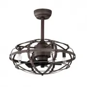
2 0 - I N C H D E R O C AT E C E I L I N G FA N
U S E A N D C A R E G U I D E
H E M - 3 0 4 2
Canopy X 1PCS
Slide - on mounting bracket
(inside canopy) X 1PCS
4.92 inch Ball/downrod
assembly X 1PCS
Coupling cover X 1PCS
Fan-Motor assembly
×
1PCS
Mounting screws
×
4
Expansion bolts
×
2
Plastic wire nut
(not to scale)
×
3
NOTE
Hardware not shown to actual size.
Hardware not shown to actual size.
Pre
-
Installation
Parts Kit
9.84 inch Ball/downrod
assembly X 1PCS
WOODEN
CEIING
Mounting
Bracket
Washers
Self
tapping
screw
For wooden ceiling, use wood
screw to drill on the wooden
beam or the "junction box" to fix
the hanging bracket(selection is
made according to actual
requirements of the customers)
SWITCH OFF THE ELECTRICAL MAINS AT THE CIRCUIT BREAKER FUSE BOX.
1) Use the Mounting Bracket as a guide, mark the spots where the 4 Self Tapping
Screws will be drilled.
2) Remove the Mounting Bracket , drill 4 holes for 3MM diameter, install the mounting
bracket onto wooden ceillng with the 4Self Tapping Screws &Washers
STEP
2
A
-
WOODEN
CEILING
For concrete ceiling, use the percussion
bit with diameter 8mm to drill holes
according to the length of expansion
screws. Then use the attached expansion
screws to fix the hanging bracket onto
the ceiling (selection is made according to
actual requirements of the customers).
STEP 1 A-CONCRETE CEILING
1 )Use the Mounting Bracket as a guide, mark the spots where the 4 Expansion Bolts
will be drilled.
SWITCH OFF THE ELECTRICAL MAINS AT THE CIRCUIT BREAKER FUSE BOX.
2 )Remove the Mounting Bracket , drill 2 holes and insert 2 Expansion Bolts into the
concrete ceiling, install the mounting bracket and secure with Flat Washers , Spring
Washers and Nuts .
IMPORTANT : SCREWS & NUTS MUST BE TIGHTENED TILL SNUG
Expansion
Bolts
Flat
Washers
N u l s
Mounting
Bracket
CÖNCRETE
CEILING
Flat
Washers
Hang the fan
Hang the fan
Install canopy
□
Carefuly feed the molor wires up though the downrod
□
Align the holes and replace hanger pin and locking pin.
□
Tighten the two colar setscrews.
□
Slip coupling cover,canopy coverand canopy onto the downrod.
□
Lift the fan motor assembly up to the mounting bracket and
seat the hanger ball in the mounting bracket socket.Rotate the
fan motor assembly until the check groove drops into the regi-
stration slot and seats firmly.The downrod should not rotate if
the is done correctly
□
Ensure the loosened screws is inserted into the key holes on
the mounting bracket.
□
Carefully raise the canopy up to the mounting bracket.Rotate
the canopy clockwise.
□
Secure the canopy by replacing the screws previously removed
and tightening the screw previously loosened
□
Place the canopy cover (if applicable)and rotate the canopy
cover clockwise until it locks into position.
Installation of the hanging bracket
Install downrod assembly
Fan On/Off
Low Level
Med Level
Hi Level
LIGHT ON/OFF
Auto off after 1hr~
4
hr
ON/OFF
WA R N I N G
: E a c h w i r e n o t s u p p l i e d w i t h t h i s f a n i s d e s i g n e d t o a c c e p t u p t o o n e 1 2 - g a u g e h o u s e w i r e a n d t w o w i r e s f r o m t h e f a n .
I f y o u h a v e l a r g e r t h a n 1 2 - g a u g e h o u s e w i r i n g o r m o r e t h a n o n e
h o u s e w i r e t o c o n n e c t t o t h e f a n w i r i n g , c o n s u l t a n e l e c t r i c i a n f o r t h e p r o p e r s i z e w i r e n u t s t o u s e .
WA R N I N G :
R e m o v e t h e r u b b e r m o t o r s t o p s o n t h e b o t t o m o f t h e f a n b e f o r e
i n s t a l l i n g t h e b l a d e s o r
t e s t i n g t h e m o t o r.
IMPORTANT: Use the plastic wire connectors(BB) supplied with your fan. Secure
the connectors with electrical tape and ensure there are no loose strands or
connections.
WARNING:Each wire not supplied with this fan is designed
to accept up to one12-gauge house wire and two wires from
the fan.If you have large than 12-gauge house wiring or
more than one house wire to connect to the fan
wiring, consult an electrician for the proper size wire nuts to
use.
IMPORTANT:
Use the plastic wire connectors(BB) supplied with your
fan.Secure the connectors with electrical tape and ensure there are no
loose strands or connections.
WARNING:Remove the rubber motor stops on the bottom of
fan before installing the blades or testing the motor.
Assembly - Hanging the Fan(continued)
Preparing for mounting
Install remote control
Preparing for mounting
1.Carefully push the canopy to the bottom of the mounting
bracket, make two sliding holes aligned to the two prominent
screws on the mounting bracket, and then turn clockwise
until tight.
2.Push the canopy ring to the bottom oft he canopy,
slide the inner holes aligned to the two prominent screws
on the mounting bracket again, and turn the canopy ring
clockwise until tight.
1:Remove the mounting bracket from the canopy by
loosening the two canopy screws located in the L shaped slots
2:Remove and save the two canopy screws in the round holes.
This will enable you to remove the mounting bracket
R-T
R-R
remote control(transmitter) X 1PCS
remote control(receiver) X 1PCS
Fastening the blade arms to the motor
INSTALLATION INSTRUCTION
Making the electrical connections
Use of remote control
C a n o p y
4 . 6 2 " B a l l / d o w n r o d a s s e m b l y
F / R
F / R
Froward/Reverse
Froward or Reverse operation:Press the button for 2sec
until there is a “BEEP”sound to chang fan rotating direction
Fanchange dirsction.(capprox.02sec)
"Loading the manual" means you need to wait until the file loads and becomes available for online reading. Some manuals are very large, and the time they take to appear depends on your internet speed.