Page 2 - Contents; PREPARATION; Correct Disposal of This Product
ENGLISH-2 Contents PREPARATION Safety precautions . . . . . . . . . . . . . . . . . . . . . . . . . . . . . . . . . . . . . . . . . . . . . . . . . . . . . . . . . . . . . . . . . . . . . . . . . . . . . . . . . . . . . . . . . . . . . . . . . . . . . . . 3Product specifications . . . . . . . . . . ...
Page 3 - Safety precautions; WARNING; Warning
ENGLISH-3 01 PREP ARA TION Safety precautions Carefully follow the precautions listed as below because they are essential to guarantee the safety of SAMSUNG product. WARNING • Always disconnect a power supply of Air-Water Heat Pump before servicing it or accessing components inside the unit. • Verif...
Page 5 - Product specifications; Accessories
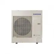
ENGLISH-5 01 PREP ARA TION Product specifications Product line-up Line-up Remark Heat pump units Chassis AE090RXEDEG AE090RXEDGG - Model name Accessories f Keep supplied accessories until the installation is finished. f Hand the installation manual over to the customer after finishing installation. ...
Page 6 - Outdoor unit specification
ENGLISH-6 Outdoor unit specification Type Unit AE090RXEDEG Power source - 1P, 220~240 VAC 50 Hz Weight (net/gross) kg 73.0/81.5 Size (WxHxD, net) mm 940 x 998 x 330 Noise (Heat/Cool, Pressure) dBA 49/49 Operating Range (Heat/Cool) °C -25~35/10~46 Refrigerant g 1,400 (R-32) Type Unit AE090RXEDGG Powe...
Page 7 - Main components
ENGLISH-7 02 INST ALLA TION Main components Dimensions(Overall) Heat pump for R-32. 1-Fan chassis f AE090RXED** 620 940 330 973 998 360 384 (Unit : mm) ki]_TW_[W^hTW\ptlozGyTZYGzwsp{Gv|{kvvyl|luUGGG^ YWYXTW_TYZGGG㝘㤸GXWaYZaX`
Page 8 - Installing the unit; Deciding on where to install the outdoor unit; Installation Guide at the seashore
ENGLISH-8 Installing the unit Deciding on where to install the outdoor unit Decide the installation location regarding the following condition and obtain the user’s approval. f The outdoor unit must not be placed on its side or upside down, as the compressor lubrication oil will run into the cooling...
Page 10 - Preparation of fire extinguisher
ENGLISH-10 Installing the unit f Note that the refrigerant has no odour. f The units are not explosion proof so they must be installed with no risk of explosion. f This product contains fluorinated gases that contribute to global greenhouse effect. Accordingly, do not vent gases into the atmosphere....
Page 11 - Ignition sources free
ENGLISH-11 02 INST ALLA TION Ignition sources free f Make sure to store the units in a place without continuously operating ignition sources (for example, open flames, an operating gas appliance or an operating electric heater). f The service engineers shall not use any ignition sources with the ris...
Page 12 - Recovery
ENGLISH-12 Installing the unit Recovery f When removing refrigerant from the system for servicing or decommissioning, it is recommended to remove the entire refrigerant. f When transferring refrigerant into cylinders, make sure that only the refrigerant recovery cylinders are used. f All cylinders u...
Page 13 - Space requirements for outdoor unit; When installing 1 outdoor unit
ENGLISH-13 02 INST ALLA TION Space requirements for outdoor unit When installing 1 outdoor unit (Unit : mm) 300 or mor e 1,500 or mor e ❋ When the air outlet is opposite the wall ❋ When the air outlet is towards the wall 300 or mor e 300 or more 600 or more 1,500 or mor e 2,000 or more ❋ When 3 side...
Page 14 - When installing more than 1 outdoor unit
ENGLISH-14 Installing the unit When installing more than 1 outdoor unit (Unit : mm) 1500 or mor e ❋ When the air outlet is towards the wall 300 or mor e 300 or more 600 or more 600 or more 600 or more ❋ When 3 sides of the outdoor unit are blocked by the wall 300 or mor e 1500 or mor e 600 or more 6...
Page 15 - Outdoor unit installation; Outdoor unit support; OUTDOOR UNIT INSTALLED ON THE WALL BY RACK
ENGLISH-15 02 INST ALLA TION Outdoor unit installation The outdoor unit must be installed on a rigid and stable base to avoid any increase in the noise level and vibration, particularly if the outdoor unit is to be installed in a location exposed to strong winds or at a height, the unit must be fixe...
Page 16 - Drain work; General area; Drain hole Φ20 x 4 ea
ENGLISH-16 Installing the unit Drain work • General area While Air-Water Heat Pump is running in heating mode, Ice can begin accumulate on the surface of condenser. To prevent Ice from growing, system go into De-frost mode and then Ice on the surface changes to water.Dropped water from condenser sha...
Page 18 - Selecting a location in cold climates
ENGLISH-18 Installing the unit Selecting a location in cold climates • When operating the unit in a low outdoor ambient temperature, be sure to follow the instructions described below. NOTE f To prevent exposure to wind, install the unit with its suction side facing the wall. f Never install the uni...
Page 19 - Electrical connections; Overall system configuration; Connection of the power cable (1 phase 2 wires); Connection of the power cable (3 phase 4 wires)
ENGLISH-19 02 INST ALLA TION Electrical connections Overall system configuration Connection of the power cable (1 phase 2 wires) Distribution board Outdoor unit Hydro unit 1 phase 2 wires 220-240 V ~ Earth Communication cable ELCB 1 phase 2 wires 220-240 V ~ Earth MCCB+ ELB Or • Install cabinet pane...
Page 20 - Connecting the cable; Power cable specifications; phase; Phase
ENGLISH-20 Connecting the cable Power cable specifications 1 phase Outdoor unit Rated Voltage Range MCA MFA Hz Volts Min Max Min. Circuit Amps. Max. Fuse Amps. AE090RXEDEG 50 220-240 198 264 22 A 27.5 A f The power cable is not supplied with Air to Water Heat pump. f Supply cords of parts of applian...
Page 21 - Specification of connection cables (common in use); Communication : M4 screw; Communication : M4 screw
ENGLISH-21 02 INST ALLA TION Specification of connection cables (common in use) Power supply Max/Min(V) Communation cable 1Φ, 220-240 V, 50 Hz ±10 % 0.75~1.5 mm², 2 wires 3Φ, 380-415 V, 50 Hz f For Power Cable, use the grade H07RN-F or H05RN-F materials. f Power supply cords of parts of appliances f...
Page 22 - Wiring diagram of power cable; When using ELB for 1 phase and 3 phase
ENGLISH-22 Connecting the cable Wiring diagram of power cable When using ELB for 1 phase and 3 phase N L3(T) L2(S) L1(R) N L 2(N) 1(L) Power Supply Electrical component box MCCB + ELB ELCB Hydro unit f 1 phase f 3 phase Communication cable Main power cable Cable clamp ❋ The appearance of the unit ma...
Page 23 - phase 2 wires
ENGLISH-23 02 INST ALLA TION 1 phase 2 wires 1 phase Earth Communication cable between Hydro unit and outdoor units Power cable Earth cable (U-Trap) Hydro unit Communication cable Circuit breaker • When removing the outer cover of the power cable, use the appropriate tools to prevent damaging the in...
Page 24 - phase 4 wires
ENGLISH-24 Connecting the cable 3 phase 4 wires L1(R) L2(S) L3(T) N 2(N) 1(L) 3 phase Earth Communication cable between Hydro and outdoor units Power cable Earth cable (U-Trap) Hydro unit Communication cable Circuit breaker NOT USE • When removing the outer cover of the power cable, use the appropri...
Page 25 - Connecting the power terminal; Installing the earth wire; Earthing the power cable; Note 1) Earthing work 3
ENGLISH-25 02 INST ALLA TION Connecting the power terminal f Connect the cables to the terminal board using the compressed ring terminal. f Connect the rated cables only. f Connect using a wrench which is able to apply the rated torque to the screws. f If the terminal is loose, fire may occur caused...
Page 26 - How to connect your extended power cables; Method 2; Method 1
ENGLISH-26 Connecting the cable How to connect your extended power cables 1. Prepare the following tools. Tools Crimping pliers Connection sleeve (mm) Insulation tape Contraction tube (mm) Spec MH-14 20xØ6.5(HxOD) Width 19mm 70xØ8.0(LxOD) Shape 2. As shown in the figure, peel off the shields from th...
Page 28 - Refrigerant piping work
ENGLISH-28 Refrigerant piping work f Install the refrigerant pipe within the maximum allowable length, difference in height and length of after the first branch pipe. f The pressure of the R-32 is high.Use only rated refrigerant pipe and follow the installation method. f Use clean refrigerant pipe W...
Page 30 - Selecting the refrigerant pipe
ENGLISH-30 Refrigerant piping work Selecting the refrigerant pipe Outdoor unit capacity (kW) Liquid side (mm) Gas side (mm) Outer diameter (mm) Minimum thickness (mm) Temper grade AE090RXEDEG ø6.35 ø15.88 ø 6.35 0.7 C1220T-0 AE090RXEDGG ø6.35 ø15.88 ø 9.52 0.7 f Install refrigerant pipe depending on...
Page 33 - Selecting the insulator of the refrigerant pipe; Insulating the refrigerant pipe
ENGLISH-33 02 INST ALLA TION Selecting the insulator of the refrigerant pipe f According to pipes size, insulate pipes on gas and liquid side by selecting appropriate insulations. f Standard condition is under a temperature of 30 °C and a humidity of 85 %. If the units are installed in extreme weath...
Page 34 - Brazing the Pipe; Replacement of Nitrogen gas
ENGLISH-34 Refrigerant piping work Insulating the refrigerant pipe f Be sure to insulate the refrigerant pipe, joints and connections with class 'o' material. f If you insulate the pipes, the condensed water does not fall from the pipes and the capacity of the Air to Water Heat Pump is improved. f C...
Page 35 - Performing the refrigerant gas leak test
ENGLISH-35 02 INST ALLA TION Performing the refrigerant gas leak test f Use a manifold gauge for R-32 to prevent the inflow of foreign substances and resist against the internal pressure. f Pressure test with dry oxygen free nitrogen only. Apply pressure to the liquid side pipe and gas side pipe wit...
Page 36 - Vacuum drying
ENGLISH-36 Refrigerant piping work Vacuum drying f Use the tools for R-32 only to prevent the inflow of foreign substances and resist against the internal pressure. f Use the vacuum pump with the check valve to prevent pump oil from flowing backward while the vacuum pump is stopped suddenly. f Use t...
Page 37 - Selecting additional refrigerant charge; Basic charge; Refrigerant Charging; Precautions on adding the R-32 refrigerant
ENGLISH-37 02 INST ALLA TION Selecting additional refrigerant charge ❋ Basic charge The basic amount of refrigerant for outdoor unit charged in factory is: Outdoor unit (Series) Factory charge(kg) AE090RXEDEG 1.4 AE090RXEDGG ❋ Charge additional refrigerant according to the total length of the pipe.E...
Page 38 - Charging refrigerant
ENGLISH-38 Refrigerant piping work Charging refrigerant f Measure the quantity of the refrigerant according to the length of the liquid side pipe. Add quantity of the refrigerant using a scale. Important information: regulation regarding the refrigerant used This product contains fluorinated greenho...
Page 39 - Adding refrigerant
ENGLISH-39 02 INST ALLA TION Adding refrigerant f Measure the quantity of the refrigerant depending on the length of the liquid side pipe. Add fixed quantity of the refrigerant using a scale. ❋ Adding refrigerants in cooling conditions Gas side Scale Liquid side Manifold gauge Service valve Outdoor ...
Page 40 - To close the valve stem; To open the valve stem
ENGLISH-40 Refrigerant piping work f Adding the heating refrigerant1) When recharging the heating refrigerant, connect the low pressure pipe from manifold gage to the suction charging port. 2) Press the function key for adding refrigerant in heating mode.3) After 20 minutes of operation, open the va...
Page 41 - Checking correct grounding; Setting the option switch and function of the keys; Testing operations
ENGLISH-41 02 INST ALLA TION Checking correct grounding If the power distribution circuit does not have a grounding or the grounding does not comply with specifications, an grounding electrode must be installed. The corresponding accessories are not supplied with the Air to Water Heat pump.1. Select...
Page 44 - Setting the option
ENGLISH-44 Setting the option switch and function of the keys Setting the option 1. Press and hold K2 to enter the option setting. (Only available when the operation is stopped) - If you enter the option setting, display will show the following. - Seg1 and Seg2 will display the number for selected o...
Page 46 - Pump down procedure; Objective of pump down; Relocation of the Air to water heat pump
ENGLISH-46 Pump down procedure Objective of pump down For product repairs and indoor unit relocation, pump down operation must be done recover the refrigerant into the outdoor unit. Cautions when performing pump down f Product limits amount of refrigerant in the outdoor unit due to slim design. f Co...
Page 48 - Completing the installation
ENGLISH-48 Completing the installation f Check the following after completing the installation. Installation Outdoor unit • Check the external surface and the inside of the outdoor unit.• Is there any possibility of short circuit?• Is the place well-ventilated and ensures space for service?• Is the ...
Page 49 - Final checks and trial operation; Inspection before test operation; Run the unit by KEY MODE or controller.
ENGLISH-49 02 INST ALLA TION Final checks and trial operation Inspection before test operation 1. Check the power cable and communication cable of the indoor and outdoor unit.2. Check the power supply between the outdoor unit and the cabinet panel. - Check the 220-240 V~ / 380-415 V~ with the voltag...
Page 50 - Troubleshooting; Error codes
ENGLISH-50 Troubleshooting • Incorrect handling of thermostat, safety valve or other valves may lead to tank rupture. When servicing the unit follow instructions carefully: • Always turn off main power supply when water supply is being shut off.• Test the free operation of the safety valve regularly...
Page 51 - THERS
ENGLISH-51 03 O THERS Display Explanation Error Source 416 Discharge of a compressor is overheated Outdoor Unit 419 OUTDOOR UNIT EEV operation error Outdoor Unit 425 Power source line missing error (only for 3-phase model) Outdoor Unit 440 Heating operation blocked (outdoor temperature over 35 °C) O...