Page 2 - TABLE OF CONTENTS; RYOBI; WHAT THIS WARRANTY COVERS:; ADDITIONAL LIMITATIONS:
2 — English Introduction ..................................................................................................................................................................... 2 Warranty .................................................................................................
Page 3 - GENERAL SAFETY RULES; READ ALL INSTRUCTIONS
3 — English GENERAL SAFETY RULES WARNING: Read and understand all instructions. Failure to follow all instructions listed below, may result in electric shock, fire and/or serious personal injury. READ ALL INSTRUCTIONS KNOW YOUR POWER TOOL. Read the operator’s manual carefully. Learn the applicatio...
Page 5 - SPECIFIC SAFETY RULES
5 — English NEVER PERFORM ANY OPERATION FREEHAND. Always place the workpiece to be cut on the miter table and position it firmly against the fence as a backstop. Always use the fence. NEVER hand hold a workpiece that is too small to be clamped. Keep hands clear of the cutting area. NEVER reach...
Page 6 - SYMBOLS; SYMBOL NAME; SYMBOL
6 — English SYMBOLS Some of the following symbols may be used on this tool. Please study them and learn their meaning. Proper interpretation of these symbols will allow you to operate the tool better and safer. Read Operator’s Manual Safety Alert No Hands Symbol SYMBOL NAME DESIGNATION/EXPLANATION V...
Page 7 - ELECTRICAL; EXTENSION CORDS; Cord Length; DOUBLE INSULATION; ELECTRICAL CONNECTION; power supply that is 120 volts, 60 Hz, AC
7 — English ELECTRICAL EXTENSION CORDS When using a power tool at a considerable distance from a power source, be sure to use an extension cord that has the capacity to handle the current the tool will draw. An undersized cord will cause a drop in line voltage, resulting in overheating and loss of p...
Page 8 - GLOSSARY OF TERMS
8 — English GLOSSARY OF TERMS Non-Through Cuts Any cutting operation where the blade does not extend completely through the thickness of the workpiece. Push Blocks (for jointer planers) Device used to feed the workpiece over the jointer planer cutterhead during any operation. This aid helps keep the...
Page 9 - FEATURES; PRODUCT SPECIFICATIONS
9 — English FEATURES Fig. 1 and 2 PRODUCT SPECIFICATIONS Blade Arbor .............................................................. 5/8 in.Blade Diameter .......................................................... 10 in.No Load Speed .................................... 5,000 r/min. (RPM)Input .........
Page 10 - LASER GUIDE
10 — English FEATURES KNOW YOUR COMPOUND MITER SAW See Figures 1 and 2. The safe use of this product requires an understanding of the information on the tool and in this operator’s manual as well as a knowledge of the project you are attempting. Before use of this product, familiarize yourself with ...
Page 11 - SPINDLE LOCK BUTTON
11 — English FEATURES The following tools (not included) are needed for making adjustments or installing the blade: TOOLS NEEDED Fig. 6 COMBINATION SQUARE FRAMING SQUARE COMBINATION WRENCHES (2) (10 mm, 12 mm) HEX KEYS (3) (3 mm, 5 mm, 6 mm) Fig. 4 Fig. 5 PADLOCK SWITCH TRIGGER SWITCH TRIGGER SPINDL...
Page 12 - LOOSE PARTS LIST
12 — English LOOSE PARTS LIST Fig. 7 WARNING: The use of attachments or accessories not listed might be hazardous and could cause serious personal injury. Blade Wrench Blade Operator’s Manual TABLE EXTENSION WORK CLAMP DUST BAG TABLE EXTENSION BLADE The following items are included with your C...
Page 13 - ASSEMBLY; MOUNTING HOLES
13 — English ASSEMBLY TRACE HOLES AT THESE LOCATIONS FOR HOLE PATTERN Fig. 8 MOUNTING SURFACE SAW BASE TRACE HOLES AT THESE LOCATIONS FOR HOLE PATTERN WARNING: Do not connect to power supply until assembly is complete. Failure to comply could result in accidental start- ing and possible serious pers...
Page 14 - Never operate the saw without all guards; LOCKING / UNLOCKING THE SAW ARM; To unlock and raise the saw arm:; DUST BAG; To remove the dust bag for emptying:
14 — English ASSEMBLY NOTE: Many of the illustrations in this manual show only portions of the compound miter saw. This is intentional so that we can clearly show points being made in the illustrations. Never operate the saw without all guards securely in place and in good operating condition. LOCKI...
Page 15 - WORK CLAMP; To install the work clamp:; TABLE EXTENSIONS
15 — English ASSEMBLY WORK CLAMP See Figure 11. WARNING: In some operations, the work clamp assembly may interfere with the operation of the blade guard assembly. Always make sure there is no interference with the blade guard prior to beginning any cutting operation to reduce the risk of serious per...
Page 16 - TO INSTALL / REPLACE THE BLADE; Do
16 — English ASSEMBLY TO INSTALL / REPLACE THE BLADE See Figures 14 - 15. WARNING: A 10 in. blade is the maximum blade capacity of the saw. Never use a blade that is too thick to allow outer blade washer to engage with the flats on the spindle. Larger blades will come in contact with the blade guard...
Page 17 - ALIGNING THE; RED
17 — English ASSEMBLY WARNING: Make sure the spindle lock button is not engaged before reconnecting saw into power source. Never engage spindle lock button when blade is rotating. DANGER: Laser radiation. Avoid direct eye contact with light source. WARNING: Use of controls or adjustments or performa...
Page 18 - REMOVING / REPLACING THE THROAT PLATE; THROAT
18 — English ASSEMBLY REMOVING / REPLACING THE THROAT PLATE See Figure 17. WARNING: The throat plate must be below the saw table. If the throat plate is too high or too low, the workpiece can catch on the uneven edges resulting in binding which could result in serious personal injury. Never operate ...
Page 19 - SQUARING THE BLADE TO THE FENCE
19 — English ASSEMBLY SQUARING THE BLADE TO THE FENCE See Figures 18 - 21. Unplug the saw. Pull the saw arm all the way down and engage the lock pin to hold the saw arm in transport position. Loosen the miter lock handle approximately one-half turn. Rotate the miter table until the pointer o...
Page 20 - SQUARING THE BLADE TO THE MITER TABLE; Positive Stop
20 — English MITER TABLE COMBINATION SQUARE BLADE MITER FENCE ASSEMBLY SCALE INDICATOR Fig. 22 INDICATOR SCREW BEVEL SCALE SQUARING THE BLADE TO THE MITER TABLE See Figures 22 - 25. Unplug the saw. Pull the saw arm all the way down and engage the lock pin to hold the saw arm in transport positio...
Page 21 - OPERATION; APPLICATIONS
21 — English OPERATION WARNING: Do not allow familiarity with tools to make you care-less. Remember that a careless fraction of a second is sufficient to inflict serious injury. WARNING: Always wear eye protection with side shields marked to comply with ANSI Z87.1. Failure to do so could result in o...
Page 22 - TO MAKE NON-SLIDING CUTS; TO MITER CUT / CROSS CUT; MITER CUT; CROSS CUT
22 — English OPERATION TO MAKE NON-SLIDING CUTS WARNING: Securely tighten the slide lock knob when making any non-sliding cuts. Failure to tighten the knob could result in the saw head moving during the cutting operation. TO MITER CUT / CROSS CUT See Figures 26 - 27. A cross cut is made by cutting a...
Page 23 - TO BEVEL CUT
23 — English Fig. 28 INDICATOR POINT OPERATION TO BEVEL CUT See Figures 28 - 29. A bevel cut is made by cutting across the grain of the workpiece with the blade angled to the workpiece. A straight bevel cut is made with the miter table set at the zero degree position and the blade set at an angle be...
Page 24 - TO COMPOUND MITER CUT; COMPOUND MITER CUT
24 — English OPERATION TO COMPOUND MITER CUT See Figures 30 - 31. A compound miter cut is a cut made using a miter angle and a bevel angle at the same time. This type of cut is used to make picture frames, cut molding, make boxes with sloping sides, and for certain roof framing cuts. To make this ty...
Page 25 - TO SUPPORT LONG WORKPIECES
25 — English 0 0 OPERATION TO SUPPORT LONG WORKPIECES See Figure 32. Long workpieces need extra supports. Supports should be placed along the workpiece so it does not sag. The support should let the workpiece lay flat on the base of the saw and work table during the cutting operation. Use the option...
Page 26 - TO SLIDE CUT; NEVER
26 — English OPERATION WARNING: Never make a cut by pulling the saw toward you as the blade can climb on top of the workpiece and come toward you. Failure to heed this warning could result in serious personal injury. TO SLIDE CUT See Figures 33 - 34. The sliding feature will cut workpieces 12 in. wi...
Page 27 - MAKING AN AUXILIARY FENCE; MUST
27 — English OPERATION MAKING AN AUXILIARY FENCE See Figure 35. Certain unusual cuts may benefit from a thicker miter fence (auxiliary fence) due to the size and position of the workpiece. The holes provided in the miter fence are there for just this purpose. The miter fence holes are used to secure...
Page 28 - PITCH; CUTTING COMPOUND MITERS
28 — English OPERATION 4 PITCH OF SIDE NUMBER OF SIDES 0° 6 M- 45.00°B- 0.00° 5° 10° 15° 20° 25° 30° 35° 40° 45° 50° 55° 60° 65° 70° 75° 80° 85° 90° 5 7 8 9 10 M- 36.00°B- 0.00° M- 30.00°B- 0.00° M- 25.71°B- 0.00° M- 22.50°B- 0.00° M- 20.00°B- 0.00° M- 18.00°B- 0.00° Each B (Bevel) and M (Miter) Set...
Page 29 - CUTTING CROWN MOLDING; Bevel
29 — English OPERATION Fig. 36 When cutting crown molding by this method, the bevel angle should be set at 33.85 ° . The miter angle should be set at 31.6 ° either right or left, depending on the desired cut for the applica-tion. See the chart below for correct angle settings and correct positioning...
Page 30 - WRONG; CLAMPING WIDE WORKPIECES; WIDE; CUTTING WARPED MATERIAL; RIGHT
30 — English OPERATION WRONG WARNING: To avoid a kickback and to avoid serious personal injury, never position the concave edge of bowed or warped material against the fence. CLAMPING WIDE WORKPIECES See Figure 39. When cutting wide workpieces, such as 2 in. x 6 in., boards should be clamped with a ...
Page 31 - ADJUSTMENTS; TO ADJUST THE BEVEL PIVOT
31 — English ADJUSTMENTS WARNING: Before performing any adjustment, make sure the tool is unplugged from the power supply. Failure to heed this warning could result in serious personal injury. The compound miter saw has been adjusted at the factory for making accurate cuts. However, some of the comp...
Page 32 - TRAVEL PIVOT ADJUSTMENT
32 — English ADJUSTMENTS TRAVEL PIVOT ADJUSTMENT The saw arm should rise completely to the up position by itself. If the saw arm does not raise by itself or if there is play in the pivot joints, have saw repaired at the nearest authorized service center. DEPTH STOP The depth stop limits the blad...
Page 33 - MAINTENANCE; GENERAL MAINTENANCE; Proceed as follows when re; CALIFORNIA PROPOSITION 65
33 — English MAINTENANCE WARNING: When servicing, use only identical replacement parts. Use of any other parts may create a hazard or cause product damage. WARNING: Always wear eye protection with side shields marked to comply with ANSI Z87.1 during product operation. If operation is dusty, also wea...
Page 34 - TABLE DES MATIÈRES; GARANTIE
2 — Français Introduction ..................................................................................................................................................................... 2 Garantie ................................................................................................
Page 35 - RÈGLES DE SÉCURITÉ GÉNÉRALES; LIRE TOUTES LES INSTRUCTIONS
3 — Français RÈGLES DE SÉCURITÉ GÉNÉRALES AVERTISSEMENT : Lire et veiller à bien comprendre toutes les instructions. Le non respect de toutes les instructions ci-dessous peut entraîner un choc électrique, un incendie et / ou des blessures graves. LIRE TOUTES LES INSTRUCTIONS V E I L L E R À B I E ...
Page 37 - DE LA POSITION MARCHE À LA POSITION ARRÊT; RÈGLES DE SÉCURITÉ PARTICULIÈRES; TOUJOURS ÊTRE ATTENTIF !
5 — Français S’ASSURER QUE LA LAME NE TOUCHE PAS LA PIÈCE. Ne jamais mettre la scie en marche si la lame touche la pièce à couper. Toujours laisser le moteur atteindre sa pleine vitesse de rotation avant de commencer la coupe. S’ASSURER QUE LA TABLE À ONGLETS ET LE BRAS DE LA SCIE (FONCTION DE B...
Page 38 - SYMBOLES; SYMBOLE
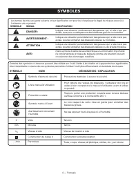
6 — Français SYMBOLES Certains des symboles ci-dessous peuvent être utilisés sur l’outil. Veiller à les étudier et à apprendre leur signification. Une interprétation correcte de ces symboles permettra d’utiliser l’outil plus efficacement et de réduire les risques. Lire le manuel d’utilisation Symbol...
Page 39 - CARACTÉRISTIQUES ÉLECTRIQUES; CORDONS PROLONGATEURS; Longueur du; DOUBLE ISOLATION; CONNEXIONS ÉLECTRIQUES
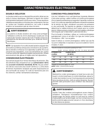
7 — Français CARACTÉRISTIQUES ÉLECTRIQUES CORDONS PROLONGATEURS Lors de l’utilisation d’un outil électrique à grande distance d’une prise secteur, veiller à utiliser un cordon prolongateur d’une capacité suffisante pour supporter l’appel de courant de l’outil. Un cordon de capacité insuffisante caus...
Page 40 - GLOSSAIRE
8 — Français GLOSSAIRE Coupes non traversantes Toute coupe avec laquelle la lame ne traverse pas complètement la pièce. Blocs poussoirs (pour dégauchisseuses/raboteuses) Dispositifs utilisés pour pousser le matériau contre la tête de coupe lors de toute opération. Ce dispositif aide à tenir la main ...
Page 41 - CARACTÉRISTIQUES; FICHE TECHNIQUE
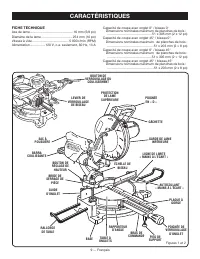
9 — Français CARACTÉRISTIQUES FICHE TECHNIQUE Axe de lame ................................................16 mm (5/8 po)Diamètre de la lame .................................. 254 mm (10 po)Vitesse à vide ........................................ 5 000 r/min (RPM)Alimentation.................120 V, c....
Page 42 - GUIDE LASER
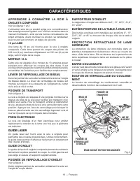
10 — Français CARACTÉRISTIQUES APPRENDRE À CONNAÎTRE LA SCIE À ONGLETS COMPOSÉS Voir les figures 1 et 2. L’utilisation sûre de ce produit exige une compréhension des renseignements figurant sur l’outil et contenus dans le manuel d’utilisation, ainsi qu’une bonne connaissance du projet entrepris. Ava...
Page 43 - BOUTON DE VERROUILLAGE DE BROCHE; OUTILS NÉCESSAIRES
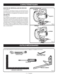
11 — Français CARACTÉRISTIQUES BOUTON DE VERROUILLAGE DE BROCHE Voir la figure 4. Le bouton de verrouillage de broche verrouille la broche en empéchant la lame de tourner. Maintenir le bouton enfoncé pour l’installation, le changement ou la dépose de la lame. GÂCHETTE Voir la figure 5. Pour empêcher...
Page 44 - LISTE DES PIÈCES DÉTACHÉES
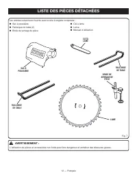
12 — Français LISTE DES PIÈCES DÉTACHÉES Fig. 7 AVERTISSEMENT : L’utilisation de pièces et accessoires non listés peut être dangereux et entraîner des blessures graves. Les articles suivant sont fournis avec la scie à onglets composés : Sac à poussière Rallonges de table (2) Bride de serrage d...
Page 45 - ASSEMBLAGE; DÉBALLAGE
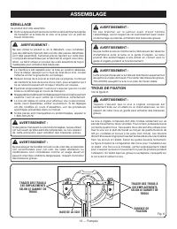
13 — Français ASSEMBLAGE TRACER DES TROUS À CES EMPLACEMENTS SELON LE GABARIT DE TROUS SURFACE DE FIXATION BASE DE LA SCIE TRACER DES TROUS À CES EMPLACEMENTS SELON LE GABARIT DE TROUS Fig. 8 DÉBALLAGE Ce produit doit être assemblé. Sortir soigneusement la scie du carton en la tenant par la poigné...
Page 46 - Ne jamais utiliser la scie; SAC À POUSSIÈRE; Pour retirer le sac et le vider:
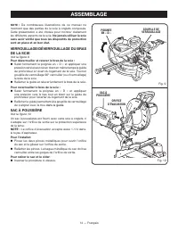
14 — Français ASSEMBLAGE NOTE : De nombreuses illustrations de ce manuel ne montrent que des parties de la scie à onglets composés. Cette présentation a été choisie pour montrer clairement les différents aspects de la scie. Ne jamais utiliser la scie sans avoir vérifié que tous les dispositifs de pr...
Page 47 - BRIDE DE SERRAGE DE PIÈCE; Installation de la bride de serrage de pièce :; RALLONGES DE TABLE; VIS DE RALLONGE
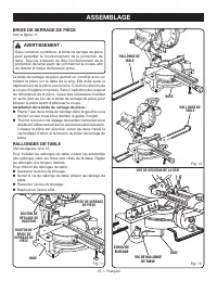
15 — Français ASSEMBLAGE BRIDE DE SERRAGE DE PIÈCE Voir la figure 11. AVERTISSEMENT : Dans certaines conditions, la bride de serrage de pièce peut perturber le fonctionnement de la protection de lame. Toujours s’assurer du libre fonctionnement de la protection de lame avant de commencer la coupe, af...
Page 48 - INSTALLATION / REMPLACEMENT DE LA LAME
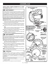
16 — Français INSTALLATION / REMPLACEMENT DE LA LAME Voir les figures 14 et 15. AVERTISSEMENT : La taille maximum de lame pouvant être utilisée sur cette scie est de 10 po. Ne jamais utiliser une lame trop épaisse pour permettre à la rondelle extérieure de la lame de s’engager sur les méplats de la ...
Page 49 - ALIGNEMENT DU; INTERRUPTOR
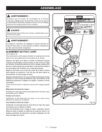
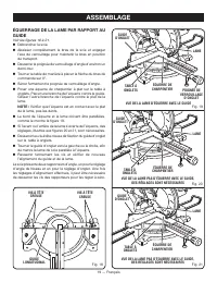
17 — Français ASSEMBLAGE AVERTISSEMENT : S’assurer que le bouton de verrouillage de la broche n’est pas engagé avant de brancher la scie sur la source d’alimentation. Ne jamais engager le bouton de verrouillage de la broche lorsque la lame est en rotation. DANGER : Rayonnement laser. Éviter tout con...
Page 50 - RÉGLAGE DU PIED DE SUPPORT; PLAQUE À
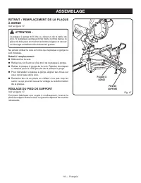
18 — Français ASSEMBLAGE RETRAIT / REMPLACEMENT DE LA PLAQUE À GORGE Voir la figure 17. ATTENTION : La plaque à gorge doit être au dessous de la table de scie. Si la plaque à gorge est trop haute ou trop basse, la pièce de bois peut accrocher les bords inégaux et causer un blocage entraînant des ble...
Page 53 - UTILISATION
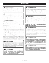
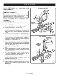
21 — Français UTILISATION AVERTISSEMENT : Ne pas laisser la familiarité avec l’outil faire oublier la prudence. Ne pas oublier qu’une fraction de seconde d’inattention peut entraîner des blessures graves. AVERTISSEMENT : Toujours porter une protection oculaire certifiée conforme à la norme ANSI Z87....
Page 55 - COUPE EN BISEAU
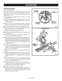
23 — Français VIS D’INDICATEUR INDICATEUR D’ÉCHELLE UTILISATION COUPE EN BISEAU Voir les figures 28 et 29. Une coupe en biseau est réalisée en travers du grain de la pièce, avec la lame en biais. Pour effectuer une coupe en biseau droite, la table à onglets doit être réglée sur 0° et la lame entre 0...
Page 56 - COUPE D’ONGLET COMPOSÉ; BRIDE DE SERRAGE
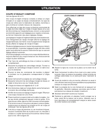
24 — Français UTILISATION COUPE D’ONGLET COMPOSÉ V oir les figures 30 et 31. Une coupe d’onglet composé consiste à utiliser un angle d’onglet et un angle de biseau simultanément. Ce type de coupe est utilisé pour la réalisation de cadres, de boîtes à pans inclinés et certains travaux de charpente. P...
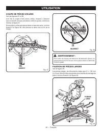
Page 57 - SUPPORT DE PIÈCES LONGUES; COUPE D’ONGLET COMPOSÉ 45° X 45°
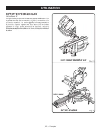
25 — Français UTILISATION SUPPORT DE PIÈCES LONGUES Voir la figure 32. Les pièces longues nécessitent un support additionnel. Les supports doivent être placés sous la pièce, de manière à ce qu’elle ne fléchisse pas. Les supports doivent permettre à la pièce de reposer à plat sur la base de la scie e...
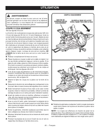
Page 58 - COUPE À COULISSEMENT; NE
26 — Français UTILISATION AVERTISSEMENT : Ne jamais couper en tirant la scie vers soi car la lame pourrait grimper sur le haut de la pièce et se déplacer vers l’opérateur. Le non-respect de cet avertissement pourrait entraîner des blessures graves. COUPE À COULISSEMENT Voir les figures 33 et 34. La ...
Page 59 - DOIT
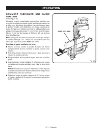
27 — Français C O M M E N T F A B R I Q U E R U N E G U I D E AUXILIAIRE Voir la figure 35. Certaines coupes inhabituelles peuvent être facilitées par un guide d’onglet plus épais (guide auxiliaire) en raison de la taille et de la position de la pièce. Les trous fournis dans le guide d’onglets sont ...
Page 60 - ANGLE; COUPE D’ONGLETS COMPOSÉS
28 — Français UTILISATION 4 ANGLE DE CÔTÉ NOMBRE DE CÔTÉS 0° 6 5° 10° 15° 20° 25° 30° 35° 40° 45° 50° 55° 60° 65° 70° 75° 80° 85° 90° 5 7 8 9 10 Chaque angle B (biseau) et O (onglet) est indiquée au 0,005 ème de degré le plus proche. RÉGLAGES D’ANGLES COMPOSÉS POUR LES CONSTRUCTIONS COURANTES COUPE ...
Page 61 - COUPE DE MOULURE COURONNÉE
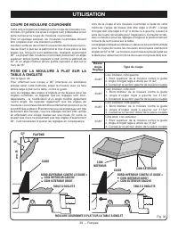
29 — Français UTILISATION Fig. 36 Lors de la coupe d’une moulure couronnée à l’aide de cette méthode, l’angle de biseau doit être réglé à 33,85°. L’angle d’onglet doit être réglé à 31,6° à droite ou à gauche, suivant le sens de coupe nécessaire pour l’application. Consulter le tab-leau ci-dessous po...
Page 62 - INCORRECT; FIXATION DE PIÈCES LARGES; CORRECT
30 — Français UTILISATION INCORRECT AVERTISSEMENT : Pour éviter les risques de rebond et de blessures graves, ne jamais placer le bord concave d’une pièce voilée ou déformée contre le guide. FIXATION DE PIÈCES LARGES Voir la figure 39. Les pièces larges, de dimensions telles que 51 x 152 mm (2 x 6 p...
Page 63 - RÉGLAGES; RÉGLAGE DU PIVOT DE BISEAU
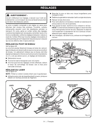
31 — Français RÉGLAGES AVERTISSEMENT : Avant d’effectuer tout réglage, s’assurer que l’outil est débranché. Le non respect de cet avertissement pourrait entraîner des blessures graves. La scie à onglets composés a été réglée en usine pour effectuer des coupes très précises. Toutefois, certains compo...
Page 64 - RÉGLAGE DU PIVOT DE BRAS; RÉGLAGES DE LA BUTÉE DE PROFONDEUR
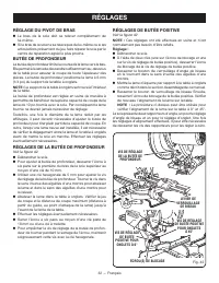
32 — Français RÉGLAGES RÉGLAGE DU PIVOT DE BRAS Le bras de la scie doit se relever complètement de lui-même. Si le bras de la scie ne se relève pas de lui-même ou si les articulations présentent du jeu, faire réparer la scie par le centre de réparation agréé le plus proche. BUTÉE DE PROFONDEUR L...
Page 65 - ENTRETIEN; ENTRETIEN GÉNÉRAL; LUBRIFICATION; REMPLACEMENT DES BALAIS; Lorsque le remplacement des balais s’avère nécessaire,; PROPOSITION 65 DE L’ÉTAT DE CALIFORNIE
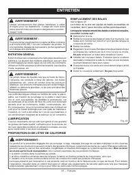
33 — Français ENTRETIEN AVERTISSEMENT : Utiliser exclusivement des pièces identiques à celles d’origine pour les réparations. L’usage de toute autre pièce pourrait créer une situation dangereuse ou endom- mager l’outil. AVERTISSEMENT : Toujours porter une protection oculaire certifiée conforme à la ...
Page 66 - NOTES
Page 67 - ÍNDICE DE CONTENIDO; LO QUE NO ESTÁ CUBIERTO:; GARANTÍA
2 — Español Introducción ..................................................................................................................................................................... 2 Garantía .................................................................................................
Page 68 - REGLAS DE SEGURIDAD GENERALES; LEA TODAS LAS INSTRUCCIONES
3 — Español REGLAS DE SEGURIDAD GENERALES ADVERTENCIA: Lea y comprenda todas las instrucciones. El incumplimiento de las instrucciones señaladas abajo puede causar descargas eléctricas, incendios y lesiones serias. LEA TODAS LAS INSTRUCCIONES FAMILIARÍCESE CON SU HERRAMIENTA ELÉCTRICA. Lea cuidado...
Page 69 - CLAVIJAS POLARIZADAS.; REGLAS DE SEGURIDAD ESPECÍFICAS
4 — Español REGLAS DE SEGURIDAD GENERALES M A N T E N G A L A S H O JA S D E C O R T E L I M P I A S Y AFILADAS. Las hojas de corte afiladas reducen al mínimo los paros y los contragolpes. LA HOJA DE CORTE CONTINÚA GIRANDO POR INERCIA DESPUÉS DE APAGARSE LA UNIDAD. NUNCA UTILICE LA UNIDAD EN U...
Page 70 - INGLETEADORA ESTÁ FALTANTE,
5 — Español NUNCA UTI LICE UN TOPE DE LONGITUD EN E L E X TREMO DE DESPERDICIOS SUELTOS DE UNA PIEZA DE TRABAJO SUJETA CON PRENSA. NUNCA sujete o doble el extremo de desperdicio de una pieza de trabajo en cualquier operación. Si se utilizan juntos una prensa para pieza de trabajo y un tope de long...
Page 71 - SÍMBOLOS; SÍMBOLO NOMBRE; SÍMBOLO
6 — Español SÍMBOLOS Es posible que se empleen en esta herramienta algunos de los siguientes símbolos. Le suplicamos estudiarlos y aprender su significado. Una correcta interpretación de estos símbolos le permitirá utilizar mejor y de manera más segura la herramienta. SÍMBOLO NOMBRE DENOMINACIÓN/EXP...
Page 72 - ASPECTOS ELÉCTRICOS; DOBLE AISLAMIENTO; CONEXIÓN ELÉCTRICA; una línea; CORDONES DE EXTENSIÓN; Longitud del
7 — Español ASPECTOS ELÉCTRICOS DOBLE AISLAMIENTO El doble aislamiento es una característica de seguridad de las herramientas eléctricas, la cual elimina la necesidad de usar el típico cordón eléctrico de tres conductores con conexión a tierra. Todas las partes metálicas expuestas están aisladas de ...
Page 73 - GLOSARIO DE TÉRMINOS
8 — Español GLOSARIO DE TÉRMINOS Cortes sin traspaso Es cualquier operación de corte en la cual la hoja de corte no traspasa completamente el espesor de la pieza de trabajo. Bloques empujadores (para cepillos de juntas) Son dispositivos empleados para avanzar la pieza de trabajo por el cepillo de ju...
Page 74 - CARACTERÍSTICAS; ESPECIFICACIONES DEL PRODUCTO
9 — Español CARACTERÍSTICAS ESPECIFICACIONES DEL PRODUCTO Árbol de la hoja de corte ................................. 16 mm (5/8 pulg.) Diámetro de la hoja .........................................254 mm (10 pulg.) Velocidad en vacío .......................................... 5 000 r/min (RPM)Corrie...
Page 75 - GUÍA LÁSER
10 — Español CARACTERÍSTICAS FAMILIARÍCESE CON LA SIERRA INGLETEA-DORA COMBINADA Vea las figuras 1 y 2. El uso seguro que este producto requiere la comprensión de la información impresa en la herramienta y en el manual del operador así como ciertos conocimientos sobre el proyecto a realizar. Antes d...
Page 76 - GUÍA DE INGLETES; HERRAMIENTAS NECESARIAS
11 — Español CARACTERÍSTICAS GUÍA DE INGLETES La guía de ingletes de la sierra ingleteadora combinada se suministra para apoyar firmemente la pieza de trabajo al efectuar todo tipo de cortes. El lado izquierdo es más largo para ofrecer mayor soporte. BOTÓN DEL SEGURO DEL HUSILLO Vea la figura 4. El ...
Page 77 - LISTA DE PIEZAS SUELTAS
12 — Español LISTA DE PIEZAS SUELTAS Fig. 7 ADVERTENCIA: El empleo de aditamentos o accesorios no enumerados arriba podría ser peligros y causar lesiones serias. Saco captapolvo Extensiones de la mesa (2) Prensa de trabajo Llave de la hoja Hoja Manual del operador EXTENSION DE LA MESA LL...
Page 78 - ARMADO; DESEMPAQUETADO
13 — Español ARMADO SEÑALE EL CENTRO DE LOS AGUJEROS EN ESTOS LUGARES SUPERFICIE DE MONTAJE BASE DE LA SIERRA SEÑALE EL CENTRO DE LOS AGUJEROS EN ESTOS LUGARES Fig. 8 DESEMPAQUETADO Este producto requiere armarse. Levante cuidadosamente de la caja la sierra sujetándola del mango de acarreo y de la...
Page 79 - Nunca; SACO CAPTAPOLVO; Para retirar el saco captapolvo con el fin de vaciarlo:
14 — Español ARMADO NOTA: En muchas de las ilustraciones de este manual se muestran sólo porciones de la sierra ingleteadora compu-esta. Se hace así deliberadamente para mostrar con claridad lo que intentamos comunicar en las ilustraciones. Nunca utilice la sierra sin todas las protecciones montadas...
Page 80 - PRENSA DE TRABAJO; EXTENSIONES DE LA MESA
15 — Español ARMADO PRENSA DE TRABAJO Vea la figura 11. ADVERTENCIA: En algunas operaciones el conjunto de la prensa de trabajo puede interferir en el movimiento del conjunto de protección de la hoja. Siempre asegúrese de que no haya interferencia en el movimiento de la protección de la hoja antes d...
Page 81 - PARA INSTALAR O REEMPLAZAR LA HOJA
16 — Español ARMADO PROTECCIÓN INFERIOR DE LA HOJA PARTE(S) PLANA(S) DEL HUSILLO TAPA DEL PERNO DE LA HOJA ARANDELA INTERIOR DE LA HOJA CON DOS PARTES PLANAS EN “D” PARA INSTALAR O REEMPLAZAR LA HOJA Vea las figuras 14 y 15. ADVERTENCIA: La sierra tiene capacidad para hojas hasta de un diámetro de 1...
Page 82 - ALI; LÍNEA ROJA
17 — Español ARMADO ADVERTENCIA: Asegúrese de que el botón del seguro del husillo no esté oprimido antes de volver a conectar la sierra al suministro de corriente. Nunca oprima el botón del seguro del husillo cuando esté girando la hoja. PELIGRO: Radiación láser. Evite todo contacto directo de los o...
Page 83 - PARA AJUSTAR PIED DE SUPPORT; PLACA DE LA
18 — Español ARMADO EXTRACCIÓN / REEMPLAZO DE LA PLACA DE GARGANTA Vea la figura 17. ADVERTENCIA: La placa de la garganta debe estar a debajo de la mesa de la sierra. Si la placa de la garganta está demasiado alta o demasiado baja, la pieza de trabajo puede engancharse en los bordes desiguales y res...
Page 84 - ESCUADRADO DE LA HOJA CON LA GUÍA
19 — Español ARMADO ESCUADRADO DE LA HOJA CON LA GUÍA Vea las figuras 18 a 21. Desconecte la sierra. Tire del brazo de la sierra completamente hacia abajo y enganche el pasador de seguridad para asegurar el brazo en la posición de transporte. Afloje la perilla de fijación de inglete aproximada...
Page 86 - FUNCIONAMIENTO; APLICACIONES
21 — Español FUNCIONAMIENTO ADVERTENCIA: No permita que su familarización con las herramientas lo vuelva descuidado. Tenga presente que un descuido de un instante es suficiente para causar una lesión grave. ADVERTENCIA: Siempre póngase protección ocular con la marca de cumplimiento de la norma ANSI ...
Page 87 - P A R A R E A L I Z A R C O R T E S N O
22 — Español FUNCIONAMIENTO P A R A R E A L I Z A R C O R T E S N O DESLIZANTES ADVERTENCIA: Apriete firmemente la perilla de fijación de la guía telescópica para realizar cortes no deslizantes. Si no se aprieta esta perilla, podría moverse el cabezal de la sierra durante la tarea de corte. PARA REA...
Page 88 - PARA CORTAR A BISEL
23 — Español FUNCIONAMIENTO PARA CORTAR A BISEL Vea las figuras 28 y 29. Un corte en bisel se efectúa cortando a través de la fibra de la pieza de trabajo con la hoja en ángulo con dicha pieza. Un corte en bisel recto se efectúa con la mesa de ingletes en la posición de cero grados y la hoja a un án...
Page 89 - PRENSA DE
24 — Español FUNCIONAMIENTO PARA EFECTUAR UN CORTE A INGLETE COMBINADO Vea las figurad 30 y 31. Un corte en bisel combinado es un corte efectuado a un ángulo de inglete y a un ángulo de bisel al mismo tiempo. Este tipo de corte se usa para elaborar marcos de cuadros, cortar molduras, elaborar cajas ...
Page 91 - PARA HACER CORTES POR DESLIZAMIENTO
26 — Español FUNCIONAMIENTO ADVERTENCIA: Nunca realice cortes tirando de la sierra hacia usted, ya que esto podría hacer que la hoja se montara sobre la pieza de trabajo, viniéndose hacia usted. La inobservan-cia de esta advertencia podría causar lesiones graves. PARA HACER CORTES POR DESLIZAMIENTO ...
Page 92 - FORMA DE HACER UNA GUÍA AUXILIAR; DEBE
27 — Español FUNCIONAMIENTO FORMA DE HACER UNA GUÍA AUXILIAR Vea la figura 35. Puede ser útil el uso de una guía de ingletes de mayor grosor (guía auxiliar) para ciertos cortes inusuales, debido al tamaño y la posición de la pieza de trabajo. Los orificios que trae la guía de ingletes son exclusivam...
Page 93 - AJUSTES DE ÁNGULOS COMBINADOS PARA ESTRUCTURAS COMUNES; CÓMO EFECTUAR CORTES A INGLETE COMBINADOS; INCLINACIÓN
28 — Español FUNCIONAMIENTO Cada cantidad, B (bisel) y M (inglete), se da con una tolerancia de 0,005°. AJUSTES DE ÁNGULOS COMBINADOS PARA ESTRUCTURAS COMUNES CÓMO EFECTUAR CORTES A INGLETE COMBINADOS Como ayuda para realizar los ajustes correctos, se suministra la siguiente tabla de ángulos combina...
Page 94 - CÓMO CORTAR MOLDURAS DE CORONA; Bisel
29 — Español FUNCIONAMIENTO Fig. 36 Al cortar molduras de corona con este método, el ángulo de bisel debe fijarse a 33,85°. El ángulo de inglete debe fijarse a 31,6°, a la derecha o izquierda, según el corte deseado para cada aplicación en particular. En la tabla mostrada a continuación encontrará l...
Page 95 - FORMA INCORRECTA; SUJECIÓN DE PIEZAS ANCHAS; FORMA CORRECTA
30 — Español FUNCIONAMIENTO FORMA INCORRECTA ADVERTENCIA: Para evitar un contragolpe y posibles lesiones graves, nunca coloque el canto cóncavo de un material arqueado o distorsionado contra la guía. SUJECIÓN DE PIEZAS ANCHAS Vea la figura 39. Al cortar piezas anchas, como las de 51 x 152 mm (2 x 6 ...
Page 96 - AJUSTES; PARA AJUSTAR DEL PIVOTE DE BISEL
31 — Español AJUSTES ADVERTENCIA: Antes de efectuar cualquier ajuste, asegúrese de que la herramienta esté desconectada del suministro de corriente. La inobservancia de esta advertencia podría causar lesiones corporales serias. La sierra ingleteadora combinada ha sido ajustada en la fábrica para pro...
Page 97 - AJUSTES DE LOS TOPES; AJUSTE DEL PIVOTE DE RECORRIDO
32 — Español AJUSTES AJUSTES DE LOS TOPES Vea la figura 42. NOTA: Estos ajustes se realizaron en la fábrica y normalmente no requieren reajustarse. Para ajustar: Desconecte la sierra. Con dos llaves (una para la tuerca de seguridad y la otra para el tornillo de ajuste del tope) afloje la tuerca ...
Page 98 - MANTENIMIENTO; MANTENIMIENTO GENERAL; Proceda como sigue cuando se requiera un reemplazo:
33 — Español MANTENIMIENTO ADVERTENCIA: Al dar servicio a la unidad, sólo utilice piezas de repuesto idénticas. El empleo de piezas diferentes puede causar un peligro o dañar el producto. ADVERTENCIA: Siempre póngase protección ocular con la marca de cumplimiento de la norma ANSI Z87.1. Si la operac...
Page 100 - MANUEL D’UTILISATION /MANUAL DEL OPERADOR; 0 in. SLIDING COMPOUND MITER SAW WITH LASER; CON GUÍA LÁSER; ou en téléphonant au
9900006298-7-13 (REV: 01) OPERATOR’S MANUAL / MANUEL D’UTILISATION /MANUAL DEL OPERADOR 10 in. SLIDING COMPOUND MITER SAW WITH LASER DE 254 mm (10 po) SCIE À ONGLETS COMBINÉS COULISSANTE AVEC LASER SIERRA INGLETEADORA COMPUESTA DESLIZANTE DE 254 mm (10 pulg.) CON GUÍA LÁSER TSS100L1 ONE WORLD TECHNO...