Parrot Uncle F3513110V - User Manual
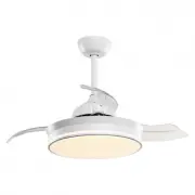
Parrot Uncle F3513110V Fan – User Manual, read for free online in PDF format. We hope this helps you resolve any issues you may have. If you have further questions, please contact us through the contact form.


INSTALLING THE FAN
BEFORE INSTALLATION
TECHNICAL INFORMATION
Installation & Operating Instructions for the
WARNING:SHUT POWER OFF AT FUSE OR CIRCUIT BREAKER
F3513
Owner’s Installation ,Manual
All rights reserved.
Made in China
Unpack your fan and check the contents.You should have followings:
THANK YOU FOR YOUR PURCHASE
SAFETY RULES
Thank you for purchasing this quality product.To ensure correct function and safety, please read and save
all instructions before using the product
SKU
Rated Voltage
Rated power(motor)
.
110-120V AC
32W LED 5500K-3000K-4000K
F3513
34W
Tools Required: Phillips screwdriver , Pair of pliers, straight slot screwdriver , adjustable wrench, step ladder , and wire cutters.
INSTALLING THE MOUNTING BRACKET
The ceiling fan must be installed in a location so that the blades are 300mm spacing from the tip of the blade to the nearest objects or walls. When hanging the Fan REMEMBER
to turn off the power. Follow the instruction below to hang your fan properly:
1. For the concrete ceiling, drill two holes in the ceiling
and secure the mounting bracket to the ceiling with two
Φ
8(
distance between the two holes should be
appropriate) expansion screws, flat washers,nuts
provided and tighten with a spanner.
2. For the wood ceiling, Secure the mounting bracket to the
ceiling is capable of carrying a load of at least 45KGS with
two long mounting screws and washers provided. Be sure
at least 30mm of the screw is threaded into the support.
3. Refer to the Fig. in right for mounting when the ceiling is
angled max. 15 degree angle.
NOTE:Hanger after the installation must be able to withstand the weight of 45kg or more.
1. To reduce the risk of electric shock, insure electricity has been turned off at the circuit breaker or fuse box
before beginning.
2. All wiring must be in accordance with the National Electrical Code and local electrical codes. Electrical
installation should be performed by a qualified licensed electrician.
3. `
WARNING: To reduce the risk of electrical shock and fire, do not use this fan with any solid-state fan speed
control device.
4. WARNING: To reduce the risk of fire, electric shock, or personal injury,mount to outlet box marked
"Acceptable for Fan Support of 45kg (99.12 lbs.) Or Less" and use mounting screws provided with the outlet
box. Most outlet boxes commonly used for the support of light fixtures are not acceptable for fan support and
may need to be replaced. Due to the complexity of the installation of this fan, a qualified licensed electrician
is strongly recommended.
5. The outlet box and support structure must be securely mounted and capable of reliably supporting a
minimum of 45KGS. Use only UL Listed outlet boxes marked FOR FAN SUPPORT.
6. The fan must be mounted with a minimum of 7 feet clearance from the trailing edge of the blades to the floor.
7.
Avoid placing objects in the path of the blades.
8. To avoid personal injury or damage to the fan and other items, be cautious when working around or cleaning
the fan.
9. Do not use water or detergents when cleaning the fan or fan blades. A dry dust cloth or lightly dampened
cloth will be suitable for most cleaning.
10. After making electrical connections, spliced conductors should be turned upward and pushed carefully up
into the outlet box. The wires should be spread apart with the grounded conductor and the equipment-
grounding conductor on one side of the outlet box.
11. Electrical diagrams are for reference only.
12. The fan is suitable for indoor use only.
Light CCT.
13.
Please do not use the tan in a specific environment like high temperature environment. high
radiation environment.lampblack or other abnormal use environments.
BEFORE INSTALLATION
Installation & Operating Instructions for the
WARNING:SHUT POWER OFF AT FUSE OR CIRCUIT BREAKER
F3513
Owner’s Installation ,Manual
All rights reserved.
Made in China
Unpack your fan and check the contents.You should have followings:
1. Mounting Bracket
2. Canopy screws
3. Canopy
4. Downrod&hanger ball
7. Bolt
6. Coupling cover
8. Lock pin
9. Top housing
10. Blades
11. Fan motor assembly
12. Base plate
13. LED
15. Wood screws
16. Expansion screws
17. Screw washers
18. Balance tapes
19. Remote control set
5. Canopy cover
15 16 17 18
19
15 16 17 18
2 4 8
hr
1
2
3
19
1. Mounting Bracket
2. Canopy screws
3. Canopy
4. Downrod&hanger ball
7. Bolt
6. Coupling cover
8. Lock pin
5. Canopy cover
9. Top housing
10. Blades
11. Fan motor assembly
12. Base plate
13. Light kit
14. Lampshade
17. Screw washers
18. Balance tapes
19. Remote control set
14. Lampshade
16. Expansion screws
15. Wood screws
1
10
11
7
9
2
3
4
6
5
8
12
13
14
1
10
11
7
9
2
3
4
6
5
8
12
13
14
"Loading the manual" means you need to wait until the file loads and becomes available for online reading. Some manuals are very large, and the time they take to appear depends on your internet speed.