Page 2 - Copyrght Notce
Preface MS-7695 Preface Preface MS-7695 Preface Copyrght Notce The materal n ths document s the ntellectual property of MICRO-STAR INTERNA- TIONAL. We take every care n the preparaton of ths document, but no guarantee s gven as to the correctness of ts contents. Our products are under contnual mprov...
Page 3 - Techncal Support
Preface MS-7695 Preface Preface MS-7695 Preface Techncal Support If a problem arses wth your system and no soluton can be obtaned from the user’s manual, please contact your place of purchase or local dstrbutor. Alternatvely, please try the followng help resources for further gudance. Vst the MSI we...
Page 4 - FCC-B Rado Frequency Interference Statement
v Preface MS-7695 Preface Preface MS-7695 Preface FCC-B Rado Frequency Interference Statement Ths equpment has been tested and found to comply wth the lmts for a Class B dgtal devce, pursuant to Part 15 of the FCC Rules. These lmts are desgned to provde reasonable protecton aganst harmful nterferenc...
Page 5 - Preface; Preface; Preface; separately for recyclng or specal dsposal.; Battery Informaton
Preface MS-7695 Preface v Preface MS-7695 Preface Calforna, USA: The button cell battery may contan perchlorate materal and requres specal handlng when recycled or dsposed of n Calforna. For further nformaton please vst:http://www.dtsc.ca.gov/hazardouswaste/perchlorate/ CAUTION: There s a rsk of exp...
Page 6 - WEEE (Waste Electrcal and Electronc Equpment) Statement; ENGLISH; schlesslch an ener lokalen Altgerätesammelstelle n Ihrer Nähe.; FRANÇAIS; эти изделия в специализированные пункты приема.
v Preface MS-7695 Preface Preface MS-7695 Preface WEEE (Waste Electrcal and Electronc Equpment) Statement ENGLISH To protect the global envronment and as an envronmentalst, MSI must re- mnd you that...Under the European Unon (“EU”) Drectve on Waste Electrcal and Elec- tronc Equpment, Drectve 2002/96...
Page 7 - ESPAÑOL; empresa autorzada para la recogda de estos resduos.; NEDERLANDS; lokale nzamelngspunten.; SRPSKI; vode možete vratt na lokalnm mestma za prkupljanje.; POLSKI
Preface MS-7695 Preface v Preface MS-7695 Preface ESPAÑOL MSI como empresa comprometda con la proteccón del medo ambente, recomenda:Bajo la drectva 2002/96/EC de la Unón Europea en matera de desechos y/o equ- pos electróncos, con fecha de rgor desde el 13 de agosto de 2005, los productos clasficados...
Page 8 - TÜRKÇE; noktalarına bırakablrsnz.; ČESKY; cclo d vta. È possble portare prodott nel pù vcno punto d raccolta
v Preface MS-7695 Preface Preface MS-7695 Preface TÜRKÇE Çevrec özellğyle blnen MSI dünyada çevrey korumak çn hatırlatır:Avrupa Brlğ (AB) Kararnames Elektrk ve Elektronk Malzeme Atığı, 2002/96/EC Kararnames altında 13 Ağustos 2005 tarhnden tbaren geçerl olmak üzere, elektrkl ve elektronk malzemeler ...
Page 11 - Englsh; Europe verson
Page 12 - Manboard Specficatons
En-2 MS-7695 Manboard Manboard Specficatons Processor Support Support AMD ® A8/A6/A4/E2-seres processors n FM1 socket (For the latest nformaton about processor, please vst http://www.ms.com/servce/cpu-support) Chpset AMD ® A75 Memory Support DDR3 1600/ 1333/ 1066 SDRAM (total 32 GB Max) 4 DDR3 DIMMs...
Page 14 - Quck Components Gude
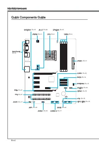
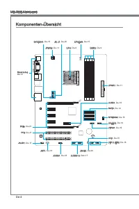
En-4 MS-7695 Manboard JPWR2, En-11 Quck Components Gude Back Panel, En-12 CPU, En-6 CPUFAN, En-15 DDR3, En-9 JPWR1, En-11 JTPM1, En-19 SATA, En-14 SYSFAN2, En-15 JFP1/ JFP2, En-16 JUSB2~3, En-17 JBAT1, En-20 JSP1, En-18 PCI, En-21 PCIe, En-21 JAUD1, En-17 JCI1, En-15 SYSFAN1, En-15 JUSB1, En-16 JCOM...
Page 15 - Mountng Screw Holes; Important
En-5 Englsh Mountng Screw Holes When you nstall the manboard, you have to place the manboard nto the chasss n the correct drecton. The locatons of screws holes on the manboard are shown as below. Refer above pcture to nstall standoffs n the approprate locatons on chasss and then screw through the ma...
Page 16 - For the latest nformaton about CPU, please vst; Overheatng
En-6 MS-7695 Manboard CPU (Central Processng Unt) When you are nstallng the CPU, make sure to nstall the cooler to prevent overheatng. If you do not have the CPU cooler, consult your dealer before turnng on the computer. For the latest nformaton about CPU, please vst http://www.ms.com/servce/cpu-sup...
Page 17 - CPU & Cooler Installaton
En-7 Englsh CPU & Cooler Installaton When you are nstallng the CPU, make sure the CPU has a cooler attached on the top to prevent overheatng. Meanwhle, do not forget to apply some thermal paste on CPU before nstallng the heat snk/cooler fan for better heat dsperson. Follow the steps below to nst...
Page 19 - Memory; compatble components, please vst
En-9 Englsh Memory These DIMM slots are used for nstallng memory modules. For more nformaton on compatble components, please vst http://www.ms.com/servce/test-report DDR3 240-pn, 1.5V 48x2=96 pn 72x2=144 pn Dual-Channel mode Populaton Rule In Dual-Channel mode, the memory modules can transmt and rec...
Page 21 - Power Supply; Ths connector s used to provde the power output to the CPU.; to ensure stable operaton of the manboard.
En-11 Englsh Power Supply ATX 24-pn Power Connector: JPWR1 Ths connector allows you to connect an ATX 24-pn power supply. To connect the ATX 24-pn power supply, make sure the plug of the power supply s nserted n the proper orentaton and the pns are algned. Then push down the power supply firmly nto ...
Page 22 - Back Panel; mouse/keyboard DIN connector s for a PS/2
En-12 MS-7695 Manboard Back Panel Mouse/Keyboard The standard PS/2 ® mouse/keyboard DIN connector s for a PS/2 ® mouse/keyboard. VGA Port The DB15-pn female connector s provded for montor. DVI-D Port The DVI-D (Dgtal Vsual Interface-Dgtal) connector allows you to connect a LCD montor. It provdes a h...
Page 24 - Connectors; to one Seral ATA devce.; occur durng transmsson.
En-14 MS-7695 Manboard Connectors Seral ATA Connector: SATA1~6 Ths connector s a hgh-speed Seral ATA nterface port. Each connector can connect to one Seral ATA devce. * The MB layout n ths figure s for reference only. SATA2 SATA1 SATA3 SATA4 SATA5 SATA6 Important Please do not fold the Seral ATA cab...
Page 25 - BIOS utlty and clear the record.
En-15 Englsh Fan Power Connectors: CPUFAN, SYSFAN1, SYSFAN2 The fan power connectors support system coolng fan wth +12V. When connectng the wre to the connectors, always note that the red wre s the postve and should be connected to the +12V; the black wre s Ground and should be connected to GND. If ...
Page 26 - The JFP1 s complant wth Intel
En-16 MS-7695 Manboard Front Panel Connectors: JFP1, JFP2 These connectors are for electrcal connecton to the front panel swtches and LEDs. The JFP1 s complant wth Intel ® Front Panel I/O Connectvty Desgn Gude. 1.Gro und 3.Su spen d LE D 5.Po wer L ED 7.No Pin 8.+ 6.- 4.+ 2.- Buzz er Spea ker 1.+ 3....
Page 28 - nterface for dgtal audo transmsson.; Seral Port Connector: JCOM1; bytes FIFOs. You can attach a seral devce.
En-18 MS-7695 Manboard S/PDIF-Out Connector: JSP1 Ths connector s used to connect S/PDIF (Sony & Phlps Dgtal Interconnect Format) nterface for dgtal audo transmsson. 11 5 V 3.VC C 2.SP DIF 1.Gro und * The MB layout n ths figure s for reference only. S/PDIF-Out Bracket (optonal) Seral Port Connec...
Page 29 - TPM module s optonal
En-19 Englsh TPM Module connector: JTPM1 (optonal) Ths connector connects to a TPM (Trusted Platform Module) module (optonal). Please refer to the TPM securty platform manual for more detals and usages. * The MB layout n ths figure s for reference only. 11 5 V 10.N o Pin 14.G roun d 8.5V Pow er 12.G...
Page 30 - Jumpers; Clear CMOS Jumper: JBAT1; jumper to clear data.; HDMI
En-20 MS-7695 Manboard Jumpers Clear CMOS Jumper: JBAT1 There s a CMOS RAM onboard that has a power supply from an external battery to keep the data of system configuraton. Wth the CMOS RAM, the system can automatcally boot OS every tme t s turned on. If you want to clear the system configuraton, se...
Page 31 - Slots; PCIe Slot
En-21 Englsh Slots PCIe Slot The PCIe slot supports the PCIe nterface expanson card. PCIe x16 Slot PCIe x1 Slot PCI (Perpheral Component Interconnect) Slot The PCI slot supports LAN card, SCSI card, USB card, and other add-on cards that comply wth PCI specficatons. 32-bt PCI Slot Important When addn...
Page 32 - BIOS Setup
En-22 MS-7695 Manboard BIOS Setup Ths chapter provdes basc nformaton on the BIOS Setup program and allows you to configure the system for optmum use. You may need to run the Setup program when: An error message appears on the screen durng the system bootng up, and requests you to run BIOS SETUP. You...
Page 33 - Control
En-23 Englsh Control Keyboard Mouse Descrpton <↑><↓> Move the cursor Select Item <←><→> Select Screen <Enter> Clck/ Double- clck the left button Select Icon/ Feld <Esc> Clck the rght button Jumps to the Ext menu or returns to the prevous from a submenu <+> I...
Page 34 - The Menu Bar
En-24 MS-7695 Manboard The Menu Bar Man Menu Use ths menu for basc system configuratons, such as tme, date etc. Advanced Use ths menu to setup the tems of the BIOS specal enhanced features, ntegrated perpherals, power management and PC health status. Overclockng Use ths menu to specfy your settngs f...
Page 36 - Overclockng
En-26 MS-7695 Manboard Overclockng Ths menu s for advanced users who want to overclock the manboard. Current CPU/ CPB/ NB/ DRAM Frequency These tems show the current frequences of CPU, CPU CPB, NB and Memory speed. Read-only. Adjust Internal Core Clock Ths tem s used to adjust the nternal core clock...
Page 40 - Software Informaton; Servce base menu : Through ths menu to lnk the MSI offically webste.
En-30 MS-7695 Manboard Software Informaton Take out the Drver/Utlty Dsc that s ncluded n the manboard package, and place t nto the optcal drve. The nstallaton wll auto-run, smply clck the drver or utlty and follow the pop-up screen to complete the nstallaton. The Drver/Utlty Dsc contans the: Drver m...
Page 41 - Deutsch; Europe Verson
Page 42 - Spezfikatonen
De-2 MS-7695 Manboard Spezfikatonen Prozessoren Unterstützt de AMD ® A8/A6/A4/E2-Sere Prozessoren für Sockel FM1 (Wetere CPU Informatonen finden Se unter http://www.ms.com/servce/cpu-support) Chpsatz AMD ® A75 Specher DDR3 1600/ 1333/ 1066 SDRAM (gesamt max. 32 GB) 4 DDR3 DIMMs (240-Pn/ 1,5V) unters...
Page 43 - Anschlüsse
De-3 Deutsch Wenn Se für Bestellungen von Zubehör Telenummern benötgen, finden Se dese auf unserer Produktsete unter http://www.ms.com/ndex.php Anschlüsse Hntere En-/ und Ausgänge 1 PS/2 Tastaturanschluss 1 PS/2 Mausanschluss 1 VGA Anschluss 1 DVI-D Anschluss** 1 HDMI Anschluss** 4 USB 2.0 Anschlüss...
Page 45 - board snd we nachfolgend gezegt.; Wchtg; Schraubenlöcher
De-5 Deutsch Schraubenlöcher für de Montage Wenn Se das Manboard zu nstalleren, müssen Se das Manboard n das Chasss n der korrekten Rchtung setzen. De Standorte von Schraubenlöchern auf dem Man- board snd we nachfolgend gezegt. Verwesen Se das obge Bld, um Abstandshalter n den entsprechenden Orten a...
Page 49 - tonen über kompatble Bautele finden Se unter
De-9 Deutsch Specher Dese DIMM-Steckplätze nehmen Arbetsspechermodule auf. De neusten Informa- tonen über kompatble Bautele finden Se unter http://www.ms.com/servce/test- report DDR3 240-polg, 1,5V 48x2=96 Pole 72x2=144 Pole Populatonsregeln für Dual-Kanal-Specher Im Dual-Kanal-Modus können Arbetssp...
Page 51 - Verbndung zu gewährlesten.
De-11 Deutsch Stromversorgung ATX 24-polger Stromanschluss: JPWR1 Mt desem Anschluss verbnden Se den ATX 24-polgen Anschluss des Netztels. Achten Se be dem Verbnden des ATX 24-polgen Stromanschlusses darauf, dass der Anschluss des Netztels rchtg auf den Anschluss an der Hauptplatne ausgerchtet st. D...
Page 52 - Rücktafel
De-12 MS-7695 Manboard Rücktafel Maus/Tastatur De Standard PS/2 ® Maus/Tastatur Stecker DIN st für ene PS/2 ® Maus/Tastatur. VGA Anschluss De DB 15-Pn Buchse dent zum Anschluss enes VGA Montors. DVI-D Anschluss Der DVI-D (Dgtal Vsual Interface-Dgtal) Anschluss erlaubt Ihnen, enen LCD Montor anzuschl...
Page 54 - Anschlüssen; schluss kann en S-ATA Gerät angeschlossen werden.; Datenverlusten während der Datenübertragung führt.
De-14 MS-7695 Manboard Anschlüssen Seral ATA Anschluss: SATA1~6 Der Anschluss st ene Hochgeschwndgketsschnttstelle der Seral ATA. Pro An- schluss kann en S-ATA Gerät angeschlossen werden. * Das MB-Layout n deser Abbldung haben nur Orenterungscharakter. SATA2 SATA1 SATA3 SATA4 SATA5 SATA6 Wchtg Btte ...
Page 55 - de Vortele der Steuerung des CPU Lüfters zu nutzen.; CPUFAN; gerufen und de Aufzechnung gelöscht werden.
De-15 Deutsch Stromanschlüsse für Lüfter: CPUFAN, SYSFAN1, SYSFAN2 De Anschlüsse unterstützen aktve Systemlüfter mt +12V. Wenn Se den Anschluss herstellen, sollten Se mmer darauf achten, dass der rote Draht der postve Pol st, und mt +12V verbunden werden sollte. Der schwarze Draht st der Erdkontakt ...
Page 56 - LEDs des Frontpanels. JFP1 erfüllt de Anforderungen des “Intel
De-16 MS-7695 Manboard Frontpanel Anschlüsse: JFP1, JFP2 Dese Anschlüsse snd für das Frontpanel. Se denen zum Anschluss der Schalter und LEDs des Frontpanels. JFP1 erfüllt de Anforderungen des “Intel ® Front Panel I/O Con- nectvty Desgn Gude”. 1.Gro und 3.Su spen d LE D 5.Po wer L ED 7.No Pin 8.+ 6....
Page 57 - Deser Anschluss entsprcht den Rchtlnen des Intel; panels. Der Anschluss entsprcht den Rchtlnen des “ Intel
De-17 Deutsch USB Vorderanschluss: JUSB2 / JUSB3 Deser Anschluss entsprcht den Rchtlnen des Intel ® I/O Connectvty Desgn Gude. Er st bestens geegnet, Hochgeschwndgkets- USB- Perpheregeräte anzuschleßen, we z.B. USB Festplattenlaufwerke, Dgtalkameras, MP3-Player, Drucker, Modems und ähnlches. 11 5 V ...
Page 58 - tragung dgtaler Audodaten verwendet.; Sereller Anschluss: JCOM1
De-18 MS-7695 Manboard S/PDIF-Ausgang: JSP1 De S/PDIF (Sony & Phlps Dgtal Interconnect Format) Schnttstelle wrd für de Über- tragung dgtaler Audodaten verwendet. 11 5 V 3.VC C 2.SP DIF 1.Gro und * Das MB-Layout n deser Abbldung haben nur Orenterungscharakter. S/PDIF-Ausgang Slotblech (optonal) S...
Page 59 - en Se btte dem TPM Plattform Handbuch.; TPM Modul st optonal
De-19 Deutsch TPM Anschluss: JTPM1 (optonal) Deser Anschluss wrd für das optonale TPM Modul (Trusted Platform Module) ver- wendt. Wetere Informatonen über den Ensatz des optonalen TPM Modules entnehm- en Se btte dem TPM Plattform Handbuch. * Das MB-Layout n deser Abbldung haben nur Orenterungscharak...
Page 60 - Steckbrücke; Metallgegenstand für kurze Zet, um de Daten zu löschen.
De-20 MS-7695 Manboard Steckbrücke Steckbrücke zur CMOS- Löschung: JBAT1 Der Onboard CMOS Specher (RAM) wrd über ene zusätzlche Bettere mt Strom versorgt, um de Daten der Systemkonfiguraton zu spechern. Er ermöglcht es dem Betrebssystem, mt jedem Enschalten automatsch hochzufahren. Wenn Se de System...
Page 61 - PCIe Steckplatz; Zusatzkarten aufnehmen, de mt den PCI-Spezfikatonen konform snd.; Folge1 Folge2 Folge3 Folge4
De-21 Deutsch Steckplätze PCIe Steckplatz Der PCIe-Steckplatz unterstützt ene Erweterungskarte mt der PCIe-Schnttstelle. PCIe x16-Steckplatz PCIe x1-Steckplatz PCI (Perpheral Component Interconnect) Steckplatz Der PCI-Steckplatz kann LAN-Karten, SCSI-Karten, USB-Karten und sonstge Zusatzkarten aufne...
Page 62 - Se zum Aufruf des BIOS SETUP aufgefordert werden.; te - 5te Stelle bezechnen de Modelnummer.; Aufruf des BIOS Setups; F11 drücken um das Bootmenü zu errechen)
De-22 MS-7695 Manboard BIOS Setup Deses Kaptel enthält Informatonen über das BIOS Setup und ermöglcht es Ihnen, Ihr System optmal auf Ihre Anforderungen enzustellen. Notwendgket zum Aufruf des BIOS besteht, wenn: Während des Bootvorgangs des Systems ene Fehlermeldung erschent und Se zum Aufruf des B...
Page 63 - Steuertasten
De-23 Deutsch Steuertasten Tastatur Maus Beschrebung <↑><↓> Move the cursor Auswahl enes Entrages <←><→> Auswahl enes Screen <Enter> Clck/ Double- clck the left button Auswahl enes Symbols/ Feldes <Esc> Clck the rght button Aufruf Ext Menü oder zurück zum Hauptmen...
Page 64 - De Menülese
De-24 MS-7695 Manboard De Menülese Man Menu In desem Menü können Se de Basskonfiguraton Ihres Systems anpassen, so z.B. Uhrzet, Datum usw. Advanced Verwenden Se deses Menü, um egene wetergehende Enstellungen an Ihrem System, ntegrerte Perpheregeräte, de Stromsparfunktonen und der PC-Gesundhetszustan...
Page 65 - Systemlestung zu laden.
De-25 Deutsch Wenn Se das BIOS Denstprogramm öffnen, folgen Se den untenstehenden An- wesungen. Laden der gespecherten Werksenstellung : Durch de Steuertasten (←, →, ↑, ↓) können Se [Restore Defaults] n [Save & Ext]-Menü wählen und drücken Se auf <Engabe>. Und dann zegt der Bldschrm de fol...
Page 70 - Servce-Bassmenü : Mt desem Menü können Se offizelle Websete des MSI; für bessere System Lestung zu erhalten.
De-30 MS-7695 Manboard Software-Informaton De m Manboard-Paket enthaltene DVD enthält alle notwendgen Treber. Um de Installaton automatsch laufen zu lassen, klcken Se enfach den Treber oder Utlty und folgen Se dem Pop-Up Schrm, um de Installaton durchzuführen. Der Treberge- brauchs-DVD enthält: Treb...
Page 71 - Franças
Page 72 - Spécficatons
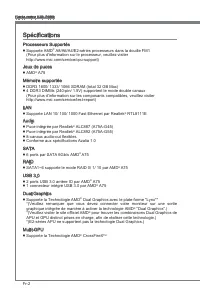
Fr-2 Carte mère MS-7695 Spécficatons Processeurs Supportés Supporte AMD ® A8/A6/A4/E2-séres processeurs dans la doulle FM1 (Pour plus d'nformaton sur le processeur, veullez vster http://www.ms.com/servce/cpu-support) Jeux de puces AMD ® A75 Mémore supportée DDR3 1600/ 1333/ 1066 SDRAM (total 32 GB M...
Page 73 - França; Connecteurs
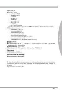
Fr-3 França s S vous désrez acheter des accessores et vous avez beson de numéros des pèces, vous pouvez chercher sur la page webste et trouver les détals sur notre adresse c- dessous http://www.ms.com/ndex.php Connecteurs Panneau arrère 1 port claver PS/2 1 port sours PS/2 1 port VGA 1 port DVI-D** ...
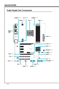
Page 74 - Gude Rapde Des Composants
Fr-4 Carte mère MS-7695 JPWR2, Fr-11 Gude Rapde Des Composants Panneau arrère, Fr-12 CPU, Fr-6 CPUFAN, Fr-15 DDR3, Fr-9 JPWR1, Fr-11 JTPM1, Fr-19 SATA, Fr-14 SYSFAN2, Fr-15 JFP1/ JFP2, Fr-16 JUSB2~3, Fr-17 JBAT1, Fr-20 JSP1, Fr-18 PCI, Fr-21 PCIe, Fr-21 JAUD1, Fr-17 JCI1, Fr-15 SYSFAN1, Fr-15 JUSB1,...
Page 76 - Surchauffe
Fr-6 Carte mère MS-7695 Processeur : CPU Quand vous nstallez le CPU, veullez vous assurer d’nstaller un ventlateur pour évter la surchauffe. S vous n’en avez pas, contactez votre revendeu pour en acheter et n- stallez-les avant d’allumer votre ordnateur. Pour plus d’nformatons sur le CPU, veullez vs...
Page 77 - Installaton du CPU et son ventlateur
Fr-7 França s Installaton du CPU et son ventlateur Quand vous nstallez le CPU, assurez-vous que le CPU sot équpé d’un ventlateur de refrodssement attaché sur le dessus pour évter la surchauffe. Néanmons, n’oublez pas d’applquer une couche d’endut thermque sur le CPU avant d’nstaller le ventla- teur ...
Page 79 - d’nformatons sur les composants compatbles, veullez vster; Pour lancer avec succès votre système, insérez
Fr-9 França s Mémore Ces emplacements DIMM sont destnés à nstaller les modules de mémore. Pour plus d’nformatons sur les composants compatbles, veullez vster http://www.ms.com/ servce/test-report DDR3 240-pn, 1.5V 48x2=96 pn 72x2=144 pn Règle de populaton en mode double-canaux En mode de canaux-doub...
Page 80 - Installaton des modules de mémore; du slot DIMM sur les côtés.; nséré dans le slot du DIMM.
Fr-10 Carte mère MS-7695 Installaton des modules de mémore Le module de mémore possède une seule encoche en son centre et ne s’adaptera que s’l est orenté de la mqnère convenable.Insérez le module de mémore à la vertcale dans le slot du DIMM. Poussez-le en- sute jusqu’à l’extrémté dorée du module de...
Page 81 - Connecteur d’almentaton ATX 24-pn : JPWR1; Ce connecteur d’almentaton sert à fournr de l’almentaton au CPU.; almentatons ATX pour garantr une opératon stable de la carte mère.
Fr-11 França s Connecteurs d’almentaton Connecteur d’almentaton ATX 24-pn : JPWR1 Ce connecteur vous permet de connecter l’almentaton ATX 24-pn. Pour cela, assurez-vous que la prse d’almentaton est ben postonnée dans le bon sens et que les gouplles soent algnées. Enfoncez alors la prse dans le conne...
Page 82 - Panneau arrère
Fr-12 Carte mère MS-7695 Panneau arrère Sours/Claver Le standard connecteur de sours/claver DIN de PS/2 ® est pour une sours ou un claver de PS/2 ® . Port VGA Le connecteur fémnn de DB15-pn est fournt pour un monteur. Port DVI-D Le connecteur DVI-D (Dgtal Vsual Interface-Dgtal) vous permet de connec...
Page 84 - être relé à un apparel de sére ATA.; pourraient se produire pendant la transmission
Fr-14 Carte mère MS-7695 Connecteurs Connecteur Séral ATA : SATA1~6 Ce connecteur est un port d’nterface de sére ATA haut débt. Chaque connecteur peut être relé à un apparel de sére ATA. * Le schéma de carte mère dans la figure n’est qu’à ttre de référence. SATA2 SATA1 SATA3 SATA4 SATA5 SATA6 Import...
Page 85 - SYSFAN2; afin de contrôler le ventlateur de l’unté centrale.
Fr-15 França s Connecteur d’almentaton du ventlateur : CPUFAN, SYSFAN1, SYSFAN2 Les connecteurs de courant du ventlateur supportent le ventlateur de refrodssement du système avec +12V. Lors du branchement des fils aux connecteurs, fates toujours en sorte que le fil rouge sot le fil postf devant être...
Page 86 - trée/sorte du panneau avant Intel
Fr-16 Carte mère MS-7695 Connecteur panneau avant : JFP1, JFP2 Ce connecteur est fourn pour la connecxon électrque aux nterrupteuts et LEDs du panneau avant. Le JFP1 est conforme au gude de concepton de la connectvté En- trée/sorte du panneau avant Intel ® . 1.Gro und 3.Su spen d LE D 5.Po wer L ED ...
Page 87 - panneau avant Intel; tout dommage possble.; Connecteur audo panneau avant : JAUD1
Fr-17 França s Connecteur USB avant : JUSB2 / JUSB3 Ce connecteur est conforme au gude de concepton de la connectvté Entrée/sorte du panneau avant Intel ® , l est déal pour reler les pérphérques d’nterface USB à haut débt tels les dsques durs externes, les apparels photo numérques, les lecteurs MP3,...
Page 88 - Format) pour une transmsson audo numérque.; Connecteur de port séral : JCOM1; reçot 16 bytes FIFOs. Vous pouvez attacher un pérphérque séral.
Fr-18 Carte mère MS-7695 Connecteur S/PDIF-Out : JSP1 Ce connecteur sert à connecter l’nterface S/PDIF (Sony & Phlps Dgtal Interconnect Format) pour une transmsson audo numérque. 11 5 V 3.VC C 2.SP DIF 1.Gro und * Le schéma de carte mère dans la figure n’est qu’à ttre de référence. Support S/PDI...
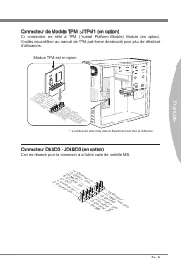
Page 89 - Module TPM est en opton
Fr-19 França s Connecteur de Module TPM : JTPM1 (en opton) Ce connecteur est rélé à TPM (Trusted Platform Module) Module (en opton). Veullez vous référer au manuel de TPM plat-forme de sécurté pour plus de détals et d’utlsatons. * Le schéma de carte mère dans la figure n’est qu’à ttre de référence. ...
Page 90 - Cavalers; Cavaler d’effacement CMOS : JBAT1; cavaler pour effacer les données.; tème est allumé cela endommagerat la carte mère.
Fr-20 Carte mère MS-7695 Cavalers Cavaler d’effacement CMOS : JBAT1 Il y a un CMOS RAM ntégré, qu possède un bloc d’almentaton almenté par une battere externe, destné à conserver les données de configuraton du système. Avec le CMOS RAM, le système peut lancer automatquement le système d’explotaton c...
Page 91 - Emplacement PCIe
Fr-21 França s Emplacements Emplacement PCIe L’emplacement PCIe supporte la carte d’extenson d’Interface PCIe. Emplacement PCIe x16 Emplacement PCIe x1 Emplacement PCI (Perpheral Component Interconnect) L’emplacement PCI supporte la carte LAN, la carte SCSI, la carte USB et d’autres cartes ajoutées ...
Page 92 - Réglage BIOS; verson BIOS. Elle est généralement sous la forme :; Entrée dans le paramétrage
Fr-22 Carte mère MS-7695 Réglage BIOS Ce chaptre donne des nformatons concernant le programme de réglage de BIOS et vous permet de configurer le système pour obtenr des performances d’utlsaton opt- mum. Vous aurez peut-être beson de lancer le programme de réglage quand : Un message d’erreur apparaît...
Page 93 - Contrôle
Fr-23 França s Contrôle Claver Sours Descrpton <↑><↓> Bouger le curseur Chosr un artcle <←><→> Chosr un écran <Enter> Clquer/ Double- clquer le bouton gauche Chosr une cône/ un domane <Esc> Clquer le bou- ton drote Retourner au menu Ext ou revenr à la page précé- ...
Page 94 - La barre menu
Fr-24 Carte mère MS-7695 La barre menu Man Menu Utlsez ce menu pour les configuratons du système de base, tel que l’heure, la date. Advanced Utlsez ce menu pour régler les objets des fonctons amélorées spécales du BIOS, les pérphérques ntégrés, la geston d’almentaton et l’état de santé de l’ordnateu...
Page 95 - pour l’utlsaton générale.
Fr-25 França s Quand vous entrez dans l’unté de réglages BIOS, suvez les procédures suvantes pour l’utlsaton générale. Load Optmzed Defaults (Chargement des réglages optmsés par défaut) : Utlsez les touches de flèche (←, →, ↑, ↓) pour chosr [Restore Defaults] dans le menu [Save & Ext], et appuye...
Page 100 - Informaton Logcel; hatez pour actver le dspostf.; melleure performance du système.
Fr-30 Carte mère MS-7695 Informaton Logcel Sortez le DVD Plote/ Servce, qu est nclus dans la boîte de la carte mère et placez-le dans le DVD-ROM. L’nstallaton va automatquement se déclencher, clquez sur le p- lote ou sur l’utltare et suvez le pop-up de l’écran pour accomplr l’nstallaton. Le DVD de P...
Page 101 - Русский
Page 102 - Характеристики системной платы
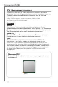
Ru-2 Системная плата MS-7695 Характеристики системной платы Поддержка процессоров Поддержка процессоров серии AMD ® A8/A6/A4/E2 с использованием разъема FM1 (Список поддерживаемых моделей см. http://www.ms.com/servce/cpu-support) Чипсет AMD ® A75 Память DDR3 1600/ 1333/ 1066 SDRAM (32ГБ максимум) 4 ...
Page 103 - Разъемы
Ru-3 Русский Для получения сведений о приобретении дополнительных компонентов и номерах деталей, воспользуйтесь поиском на нашем сайте http://www.ms.com/ndex.php Разъемы Разъемы на задней панели I/O 1 разъем PS/2 клавиатуры 1 разъем PS/2 мыши 1 порт VGA 1 порт DVI-D** 1 порт HDMI** 4 порта USB 2.0 2...
Page 104 - Краткое описание компонентов
Ru-4 Системная плата MS-7695 JPWR2, Ru-11 Краткое описание компонентов Задняя панель, Ru-12 ЦП, Ru-6 CPUFAN, Ru-15 DDR3, Ru-9 JPWR1, Ru-11 JTPM1, Ru-19 SATA, Ru-14 SYSFAN2, Ru-15 JFP1/ JFP2, Ru-16 JUSB2~3, Ru-17 JBAT1, Ru-20 JSP1, Ru-18 PCI, Ru-21 PCIe, Ru-21 JAUD1, Ru-17 JCI1, Ru-15 SYSFAN1, Ru-15 ...
Page 107 - Установка ЦП и вентилятора
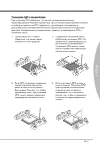
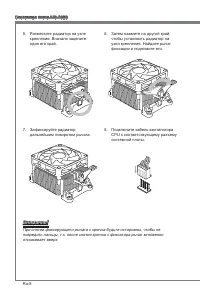
Ru-7 Русский Установка ЦП и вентилятора При установке CPU убедитесь, что на нем установлен вентилятор, предотвращающий перегрев процессора. При установке радиатора/вентилятора не забудьте нанести на CPU термопасту, улучшающую теплопередачу. Для правильной установки вентилятора и процессора выполните...
Page 109 - Слоты DIMM используются для установки модулей памяти. Подробную
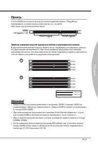
Ru-9 Русский Память Слоты DIMM используются для установки модулей памяти. Подробную информацию о совместимых компонентах см. на сайте http://www.ms.com/servce/test-report DDR3 240 контактов / 1,5 В 48x2=96 контактов 72x2=144 контакта Правила установки модулей памяти для работы в двухканальном режиме...
Page 110 - Установка модулей памяти; модуля в гнезде пластиковые защелки с обоих концов гнезда DIMM
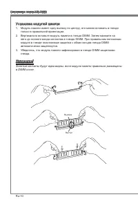
Ru-10 Системная плата MS-7695 Установка модулей памяти Модуль памяти имеет одну выемку по центру, его можно вставить в гнездо только в правильной ориентации.Вертикально вставьте модуль памяти в гнездо DIMM. Затем нажмите на него до полного входа контактов в гнездо DIMM. При правильном положении моду...
Page 111 - Данный разъем используется для подачи питания на процессор.
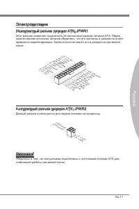
Ru-11 Русский Электропитание 24-контактный разъем питания ATX: JPWR1 Этот разъем позволяет подключить 24-контактный разъем питания ATX. Перед подключением источника питания убедитесь, что его контакты и разъем на плате правильно сориентированы. Затем плотно вставьте его в разъем на системной плате. ...
Page 112 - Разъемы на задней панели
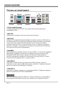
Ru-12 Системная плата MS-7695 Разъемы на задней панели Разъем мыши/клавиатуры Стандартные разъемы DIN PS/2 ® для подключения мыши/клавиатуры с интерфейсом PS/2 ® . Порт VGA Разъем DB15 гнездового типа для подключения монитора. Порт DVI-D Разъем DVI-D (цифровой видеоинтерфейс) позволяет подключить ЖК...
Page 114 - разъему Seral ATA можно подключить одно устройство Seral ATA.
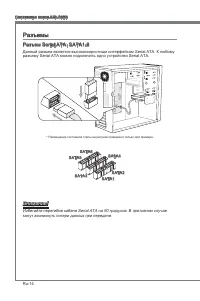
Ru-14 Системная плата MS-7695 Разъемы Разъем Seral ATA: SATA1-6 Данный разъем является высокоскоростным интерфейсом Seral ATA. К любому разъему Seral ATA можно подключить одно устройство Seral ATA. * Размещение системной платы на рисунке приведено только для примера. SATA3 SATA4 SATA5 SATA6 SATA2 SA...
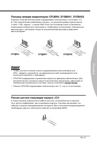
Page 115 - Разъем датчика открывания корпуса: JCI1
Ru-15 Русский Разъемы питания вентиляторов: CPUFAN, SYSFAN1, SYSFAN2 Разъемы питания вентиляторов поддерживают вентиляторы с питанием +12 В. При подключении необходимо помнить, что красный провод подключается к шине +12В, черный – к земле GND. Если на системной плате установлена микросхема аппаратно...
Page 116 - Выносная планка USB 3.0
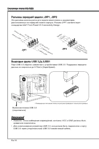
Ru-16 Системная плата MS-7695 Разъемы передней панели: JFP1, JFP2 Эти разъемы используются для подключения кнопок и индикаторов, расположенных на передней панели корпуса. Разъем JFP1 соответствует стандартам Intel ® Front Panel I/O Connectvty Desgn. 1.Gro und 3.Su spen d LE D 5.Po wer L ED 7.No Pin ...
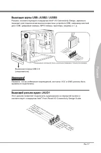
Page 117 - Разъем, соответствующий стандартам Intel; Выносная планка USB 2.0; Выносной разъем аудио: JAUD1; соответствует стандартам Intel
Ru-17 Русский Выносные порты USB: JUSB2 / JUSB3 Разъем, соответствующий стандартам Intel ® I/O Connectvty Desgn, идеально подходит для подключения высокоскоростных устройств USB, например жесткий диск USB, цифровые камеры, МРЗ плееры, принтеры, модемы и т. д. 11 5 V 1.VC C 3.US B0- 10.N C 5.US B0+ 7...
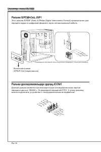
Page 118 - передачи аудио в цифровам формате через оптоволоконный кабель.; Выносная планка; Разъем последовательного порта: JCOM1; можно подключить устройство c последовательным интерфейсом.
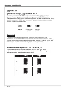
Ru-18 Системная плата MS-7695 Разъем S/PDIF-Out: JSP1 Этот разъем S/PDIF (Sony & Phlps Dgtal Interconnect Format) предназначен для передачи аудио в цифровам формате через оптоволоконный кабель. 11 5 V 3.VC C 2.SP DIF 1.Gro und * Размещение системной платы на рисунке приведено только для примера....
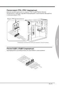
Page 119 - Данный разъем подключается к модулю TPM (Trusted Platform Module)
Ru-19 Русский Разъем модуля ТРМ: JTPM1 (опционально) Данный разъем подключается к модулю TPM (Trusted Platform Module) (опционально). За более подробной информацией и назначениями обращайтесь к описанию модуля TPM. * Размещение системной платы на рисунке приведено только для примера. 11 5 V 10.N o P...
Page 120 - Перемычки; Перемычка очистки данных CMOS: JBAT1
Ru-20 Системная плата MS-7695 Перемычки Перемычка очистки данных CMOS: JBAT1 На плате установлена CMOS память с питанием от батарейки, хранящая данные о конфигурации системы. Данные, хранящиеся в CMOS памяти, требуются компьютеру для загрузки операционной системы при включении. Если требуется очисти...
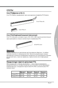
Page 121 - Слот PCIe x1; Слот PCI (Perpheral Component Interconnect); карты расширения, которые соответствуют спецификации PCI.; Маршрутизация запросов прерывания PCI; Порядок1 Порядок2 Порядок3 Порядок4
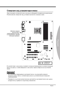
Ru-21 Русский СЛОТЫ Слот PCI Express (x16/ x1) Слот PCI Express поддерживает карты расширения интерфейса PCI Express. Слот PCIe x16 Слот PCIe x1 Слот PCI (Perpheral Component Interconnect) Слот PCI позволяет установить карты LAN, SCSI, USB и другие дополнительные карты расширения, которые соответств...
Page 122 - Настройка BIOS; Этот режим может потребоваться в следующих случаях:; Вход в режим настройки
Ru-22 Системная плата MS-7695 Настройка BIOS В этой главе приводятся основные сведения о режиме настройки BIOS (BIOS SETUP), который позволяет установить оптимальную конфигурацию системы. Этот режим может потребоваться в следующих случаях: Во время загрузки системы появляется сообщение об ошибке с т...
Page 123 - Управление
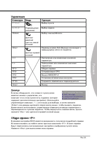
Ru-23 Русский Управление Клавиатура Мышь Описание <↑><↓> Перемещение указателя Выбор пункта <←><→> Выбор экрана <Enter> Щелчок/ двойной щелчок левой кнопкой Выбор значка/области <Esc> Щелчок правой кнопкой Переход в меню Ext (Выход) или возврат к предыдущему меню ...
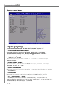
Page 124 - Верхняя строка меню; Данное меню используется для настройки параметров специальных
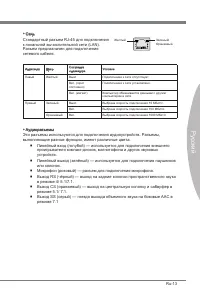
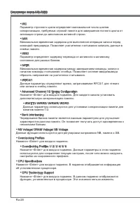
Ru-24 Системная плата MS-7695 Верхняя строка меню Man Menu (Главное Меню) Это меню базовых настроек системы, таких как дата, время и т. п. Advanced (Дополнительные функции) Данное меню используется для настройки параметров специальных дополнительный функций BIOS , встроенных периферийных устройств, ...
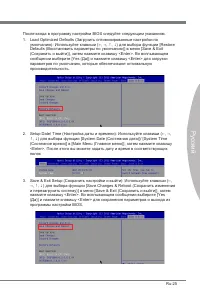
Page 125 - Load Optmzed Defaults (Загрузить оптимизированные настройки по
Ru-25 Русский После входа в программу настройки BIOS следуйте следующим указаниям. Load Optmzed Defaults (Загрузить оптимизированные настройки по умолчанию): Используйте клавиши (←, →, ↑, ↓) для выбора функции [Restore Defaults (Восстановить параметры по умолчанию)] в меню [Save & Ext (Сохранить...
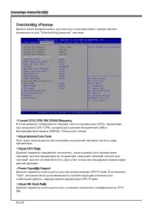
Page 126 - Overclockng «Разгон»; Adjust Internal Core Clock
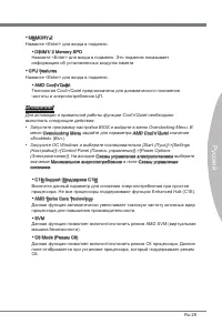
Ru-26 Системная плата MS-7695 Overclockng «Разгон» Данное меню предназначено для опытных пользователей и предоставляет возможности для “Overclockng (разгона)” системы. Current CPU/ CPB/ NB/ DRAM Frequency В этом разделе отображается текущая частота процессора (CPU), процессора под нагрузкой (CPU CPB...
Page 130 - Сведения о программном обеспечении
Ru-30 Системная плата MS-7695 Сведения о программном обеспечении Установите в привод оптических дисков прилагаемый к системной плате компакт диск «Drver/Utlty». Установка запустится автоматически. Выберите драйвер или служебную программу и следуйте инструкциям на экране для завершения установки. Сод...