MasterCool ADA5112 - User Manual
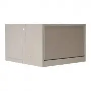
This installation and operation manual covers single-inlet evaporative coolers, focusing on their setup, maintenance, and troubleshooting to ensure safe and efficient performance. The document addresses key areas like electrical wiring (including 120V/240V connections, grounding, and amperage adjustments), water-cooling system installation (flood valves, overflow protection, and scale prevention), seasonal maintenance (filter cleaning, bearing lubrication, pump checks), and ventilation requirements for optimal airflow. It also includes troubleshooting guides for common issues such as motor cycling, inadequate cooling, or leaks, along with model-specific technical specifications and exploded diagrams of component assemblies.


Table of Contents:
- Page 1 – Introduction to Installation and Operation
- Page 2 – Cooler Installation Procedures
- Page 3 – Electrical Connection Wiring Diagrams
- Page 4 – Water-Cooled Unit Installation
- Page 5 – Operational Adjustments and Ventilation Methods
- Page 6 – Seasonal Maintenance Procedures
- Page 7 – Technical Specifications and Troubleshooting
- Page 8 – Limited Warranty Policy
- Page 9 – Evaporative Cooler Overview
- Page 10 – Motor and Component Assembly
- Page 11 – Detailed Electrical Wiring Instructions
- Page 12 – Water Connection Assembly
- Page 13 – Water-Cooled Operation and Testing
- Page 14 – Maintenance and Component Cleaning
- Page 15 – Motor Specifications and Storage Preparation
- Page 16 – Fault Location Troubleshooting
- Page 17 – Parts Replacement Guide
- Page 18 – Parts List for Down Discharge Configuration
- Page 19 – Down Discharge Configuration Diagram
- Page 20 – Parts List for Side Discharge Configuration
- Page 21 – Side Discharge Configuration Diagram
- Page 22 – Parts List for Up Discharge Configuration
- Page 23 – Up Discharge Configuration Diagram
- Page 24 – Limited Warranty Information
SINGLE INLET EVAPORATIVE COOLERS
INSTALLATION & OPERATION MANUAL
ADA51
ASA51
AUA51
ADA5112
ASA5112
AUA5112
ADA71
ASA71
AUA71
ADA7112
ASA7112
AUA7112
Circle the model of your cooler and record the serial number.
Encierrre con un circulo el modelo de su enfriador y escribe el
número de série.
Serial Number:
Número de série:
TABLE OF CONTENTS
Safety Instructions ......................................................... 1
How Evaporative Coolers Work ..................................... 1
Installation ..................................................................... 2
Operation ....................................................................... 5
Air Balancing Methods ........................................... 5
Maintenance .................................................................. 6
Specifi cation Tables ....................................................... 7
Troubleshooting ............................................................. 7
Limited Warranty ........................................................... 8
Tabla de Contenido En Español
.................. 9
Illustrated Parts List / Ilustrado
Lista de Piezas de Repuesto
(English / Español) ...................................................... 17
Garantía Limitada ........................................................ 24
Date of Purchase:
Fecha de compra:
READ AND SAVE THESE INSTRUCTIONS
SAFETY RULES
1. Read all instructions carefully.
2. Electrical connections should be done by a qualifi ed electrician,
so that all electrical wiring will conform to your local codes.
3. Always turn OFF POWER and UNPLUG motor and pump inside
the cooler before installing or performing any maintenance.
4. Your cooler will run on either 120V or 240V A.C., single phase,
60 Hz (cycle) current.
5. Motor and pump have a grounded, molded plug and an automatic
thermal overload switch which will shut motor off when it
overheats. The motor will restart automatically when it cools
down.
WARNING:
To reduce the risk of fi re or electric shock, do not use
this fan with any “solid-state fan speed control device.”
PN 110498-2
REV. 3-15
READ CAREFULLY ALL OF THIS MANUAL BEFORE INSTALLING THE UNIT
Evaporative cooling is nature’s way of cooling. When air is
moved over a wet surface, water is evaporated and heat is
absorbed. When stepping out of swimming pool with the
wind blowing, evaporative cooling makes you feel cool, even
though the air may be warm.
This unit works on the same principle. Air is drawn across
wet fi lter pads where the air is cooled by evaporation and then
circulated throughout the building. It is this combination of
cooled air and the movement of air over the skin which makes
it feel cool.
Unlike refrigeration systems which recirculate the air, an
evaporative cooler continually brings in fresh air while
exhausting old air. You are completely replacing the air every
2 to 4 minutes by opening windows or doors, by using Up-
Dux
®
ceiling vents, or a combination of both. The air is always
fresh, not stale, laden with smoke and odors as happens with
refrigerated air conditioning.
HOW EVAPORATIVE COOLERS WORK
"Loading the manual" means you need to wait until the file loads and becomes available for online reading. Some manuals are very large, and the time they take to appear depends on your internet speed.
Was this manual helpful?
About this manual
- Brand
- MasterCool
- Model
- ADA5112
- Document type
- User Manual
- Category
- Evaporative Cooler
- Language(s)
- English, Spanish
- Pages
- 24
- File size
- 1.1 MB
- Format
Summary
Model selection guide, table of contents, explanation of evaporative cooler operation with airflow principles, and safety rules for installation and operation.
Installation instructions including safety cautions, required tools, procedures for separating unit sections, motor installation with wiring, and pulley setup.
Instructions for electrical connection, wiring diagrams for 120V and 240V systems, wire color codes, terminal connections for motors and pumps, and grounding precautions.


