Page 2 - Thank you for purchasing Kapro’s 862 Prolaser; APPLICATIONS; Cross is a laser level with 2 red diodes.; NOTE; Keep this user manual for future reference.
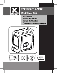
2 Thank you for purchasing Kapro’s 862 Prolaser ® Cross. You now own one of the most advanced laser tools available. This manual will show you how to get the most out of your laser tool. APPLICATIONS The 862 Prolaser ® Cross is a laser level with 2 red diodes. The laser is innovatively designed for ...
Page 3 - CONTENTS
3 CONTENTS • Features 4 • Safety instructions 5-6 • Battery installation & Safety 7-8 • Overview 9 • Operating instructions 10-11 • Maintenance 12 • Field calibration test 13-18 • Specifications 19 • Warranty 20
Page 4 - FEATURES; • Compact size – fits in your toolbox.; This device contains precision components
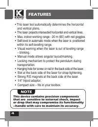
4 FEATURES • This laser tool automatically determines the horizontal and vertical plans. • The laser projects intersected horizontal and vertical lines. • Max. indoor working range - 20 m (65’) with red goggles. • Self-level in automatic mode when the laser is positioned within its self-leveling ran...
Page 5 - SAFETY INSTRUCTIONS; WARNING; The red goggles are intended to enhance
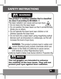
5 SAFETY INSTRUCTIONS WARNING This product is emitting radiation that is classified As class II according to EN 60825 -1 The laser radiation can cause serious eye injury • Do not stare into the laser beam • Do not position the laser beam so that it unintentionally blinds you or others. • Do not oper...
Page 6 - flammable liquids, gases or dust. Sparks from the tool can
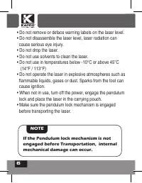
6 • Do not remove or deface warning labels on the laser level.• Do not disassemble the laser level, laser radiation can cause serious eye injury.• Do not drop the laser.• Do not use solvents to clean the laser.• Do not use in temperatures below -10°C or above 45°C (14°F / 113°F)• Do not operate the ...
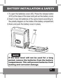
Page 7 - BATTERY INSTALLATION & SAFETY
7 • Do not remove or deface warning labels on the laser level.• Do not disassemble the laser level, laser radiation can cause serious eye injury.• Do not drop the laser.• Do not use solvents to clean the laser.• Do not use in temperatures below -10°C or above 45°C (14°F / 113°F)• Do not operate the ...
Page 9 - OVERVIEW; Laser output window; a. Automatic Mode; Operation LED indicator
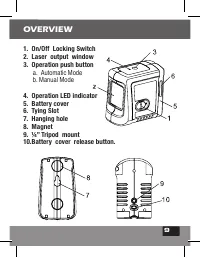
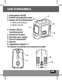
9 OVERVIEW 1. On/Off Locking Switch 2. Laser output window 3. Operation push button a. Automatic Mode b. Manual Mode 4. Operation LED indicator 5. Battery cover 6. Tying Slot 7. Hanging hole 8. Magnet 9. ¼” Tripod mount 10.Battery cover release button.
Page 10 - OPERATING INSTRUCTIONS; flat Vibration free surface or on a tripod.; ON; operation push button; OFF; position, this will lock the
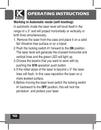
10 OPERATING INSTRUCTIONS Working in Automatic mode (self-leveling): In automatic mode the laser level will level itself in the range of ± 3° and will project horizontally or vertically or both lines simultaneously.1. Remove the laser from the case and place it on a solid flat Vibration free surface...
Page 11 - Working in Manual mode:; disabled and the laser lines can be set at any slope required.
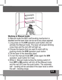
11 OPERATING INSTRUCTIONS Working in Manual mode: In Manual mode the 862’s self-leveling mechanism is disabled and the laser lines can be set at any slope required. 1. Long press on the V/H operation push button (#3) will activate the Manual mode. The laser will project blinking cross lines and the ...
Page 12 - MAINTENANCE; • To maintain the accuracy of your project, check
12 MAINTENANCE • To maintain the accuracy of your project, check the accuracy of your laser level according to the field calibration tests procedures.• Change the batteries when the laser beams begin to dim. • Wipe the aperture lens and the body of the laser level with a clean soft cloth. Do not use...
Page 13 - To do so first check the height accuracy of the horizontal; Checking the Height Accuracy of the Horizontal Line.; FIELD CALIBRATION TEST
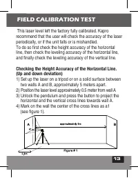
13 MAINTENANCE This laser level left the factory fully calibrated. Kapro recommend that the user will check the accuracy of the laser periodically, or if the unit falls or is mishandled. To do so first check the height accuracy of the horizontal line, then check the leveling accuracy of the horizont...
Page 15 - mm, otherwise to send the laser level to a qualified; Checking the Level Accuracy of Horizontal Line.
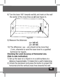
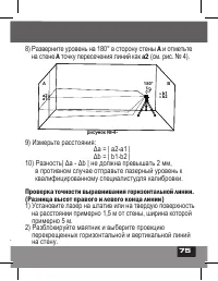
15 8) Turn the laser 180° towards wall A , and mark on the wall the center of the cross lines as a2 (see figure 4). 9) Measure the distances: Δa= |a2 - a1 | Δb= | b1 - b2 | 10) The difference | Δa – Δb| should not be more than 2 mm, otherwise to send the laser level to a qualified technician for rep...
Page 17 - than 1 mm otherwise to send the laser level to a qualified; Checking the Accuracy of the Vertical line.
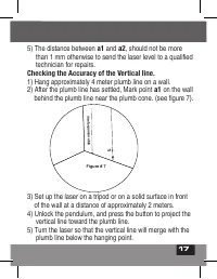
17 5) The distance between a1 and a2 , should not be more than 1 mm otherwise to send the laser level to a qualified technician for repairs. Checking the Accuracy of the Vertical line. 1) Hang approximately 4 meter plumb line on a wall. 2) After the plumb line has settled, Mark point a1 on the wall ...
Page 18 - qualified technician for repairs.; SPECIFICATIONS
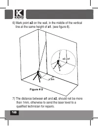
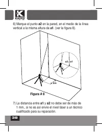
18 6) Mark point a2 on the wall, in the middle of the vertical line at the same height of a1 . (see figure 8). 7) The distance between a1 and a2 , should not be more than 1mm, otherwise to send the laser level to a qualified technician for repairs. a1 X 2m X a2 X Figure # 8 SPECIFICATIONS
Page 20 - WARRANTY; CE CONFORMITY CERTIFICATE; is in accordance with the requirements of the Community
20 WARRANTY This product is covered by a two-year limited warranty against defects in materials and workmanship. It does no cover products that are used improperly, altered or repaired without Kapro approval. In the event of a problem with the laser level you have purchased, please return the produc...
Page 22 - APLICACIONES; NOTA
22 Gracias por su compra del Kapro 862 Prolaser ® Cross. Usted posee ahora una de las herramientas láser más avanzadas disponibles. Este manual le mostrará cómo sacar el máximo provecho de su herramienta láser. APLICACIONES El 862 Prolaser ® Cross es un nivel láser con 2 diodos rojos. El láser está ...
Page 23 - CONTENIDO
23 CONTENIDO • Características 24 • Instrucciones de seguridad 25-26 • Instalación de baterías y Seguridad 27-28 • Visión general 29 • Instrucciones de operación 30-31 • Mantenimiento 32 • Prueba de calibración de campo 33-38 • Especificaciones 39 • Garantía 40
Page 24 - CARACTERÍSTICAS; • Mecanismo de bloqueo para proteger el péndulo durante; Este dispositivo contiene componentes
24 CARACTERÍSTICAS • Esta herramienta láser determina automáticamente los planos horizontal y vertical. • El láser proyecta la intersección de líneas horizontales y verticales. • Máx. alcance en trabajos de interiores - 20 m (65') con gafas de color rojo. • Auto-nivelación en modo automático cuando ...
Page 25 - INSTRUCCIONES DE SEGURIDAD; ADVERTENCIA; (California Health & Safety Code Section; Las gafas de color rojo están destinadas a
25 • Esta herramienta láser determina automáticamente los planos horizontal y vertical. • El láser proyecta la intersección de líneas horizontales y verticales. • Máx. alcance en trabajos de interiores - 20 m (65') con gafas de color rojo. • Auto-nivelación en modo automático cuando el láser se colo...
Page 27 - INSTALACIÓN DE BATERÍAS Y
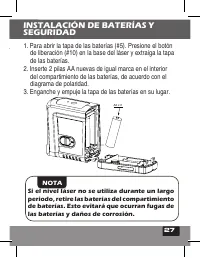
27 • No quite ni destruya las etiquetas de advertencia del nivel láser. • No desarme el nivel láser, la radiación láser puede causar lesiones oculares graves.• No deje caer el láser.• No utilice disolventes para limpiar la unidad láser.• No debe usarse en temperaturas inferiores a -10°C o superiores...
Page 28 - Las baterías pueden deteriorarse, producir
28 ADVERTENCIA: Las baterías pueden deteriorarse, producir fugas o explosiones, y pueden causar lesiones o incendios.1. No acorte los terminales de las baterías.2. No recargue las baterías alcalinas.3. No mezcle baterías viejas y nuevas.4. No deseche las baterías en la basura hogareña.5. No deseche ...
Page 29 - VISIÓN GENERAL; a. Modo automático
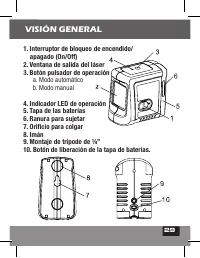
29 VISIÓN GENERAL 1. Interruptor de bloqueo de encendido/ apagado (On/Off) 2. Ventana de salida del láser 3. Botón pulsador de operación a. Modo automático b. Modo manual 4. Indicador LED de operación 5. Tapa de las baterías 6. Ranura para sujetar 7. Orificio para colgar 8. Imán 9. Montaje de trípod...
Page 30 - Empuje el interruptor de bloqueo #1 hacia; . El nivel láser generará; bloqueará el péndulo y protegerá su láser.
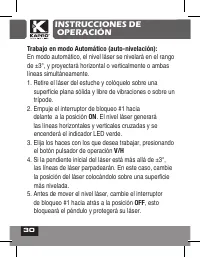
30 INSTRUCCIONES DE OPERACIÓN Trabajo en modo Automático (auto-nivelación): En modo automático, el nivel láser se nivelará en el rango de ±3°, y proyectará horizontal o verticalmente o ambas líneas simultáneamente. 1. Retire el láser del estuche y colóquelo sobre una superficie plana sólida y libre ...
Page 31 - Trabajo en modo Manual:; cualquier pendiente que se requiera.; interruptor de bloqueo #1 de
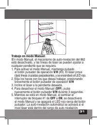
31 INSTRUCCIONES DE OPERACIÓN Trabajo en modo Manual: IEn modo Manual, el mecanismo de auto-nivelación del 862 está desactivado, y las líneas de láser se pueden ajustar a cualquier pendiente que se requiera. 1. Para activar el modo Manual, mantenga pulsado ` el botón pulsador de operación V / H (#3)...
Page 32 - MANTENIMIENTO; • Para mantener la exactitud de su proyecto,; PRUEBA DE CALIBRACIÓN DE CAMPO
32 MANTENIMIENTO • Para mantener la exactitud de su proyecto, verifique la precisión de su nivel láser de acuerdo con los procedimientos de pruebas de calibración de campo.• Cambie las baterías cuando los rayos láser comiencen a atenuarse.• Limpie el lente de apertura y el cuerpo del nivel láser uti...
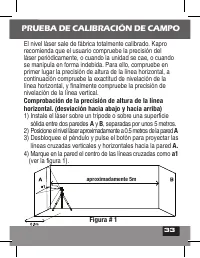
Page 33 - recomienda que el usuario compruebe la precisión del; Comprobación de la precisión de altura de la línea; ) Instale el láser sobre un trípode o sobre una superficie
33 MANTENIMIENTO El nivel láser sale de fábrica totalmente calibrado. Kapro recomienda que el usuario compruebe la precisión del láser periódicamente, o cuando la unidad se cae, o cuando se manipula en forma indebida. Para ello, compruebe en primer lugar la precisión de altura de la línea horizontal...
Page 35 - Comprobación de la precisión de nivelación de la línea
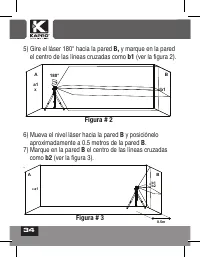
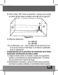
35 8) Gire el láser 180° hacia la pared A , y marque en la pared el centro de las líneas cruzadas como a2 (ver la figura 4). 9) Mida las distancias: Δa= |a2 - a1 | Δb= | b1 - b2 | 10) La diferencia | Δa – Δb| no debe ser de más de 2 mm., si no es así envíe el nivel láser a un técnico cualificado par...
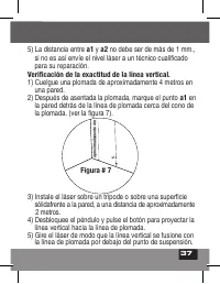
Page 37 - si no es así envíe el nivel láser a un técnico cualificado; Verificación de la exactitud de la línea vertical.; ) Después de asentada la plomada, marque el punto
37 5) La distancia entre a1 y a2 no debe ser de más de 1 mm., si no es así envíe el nivel láser a un técnico cualificado para su reparación. Verificación de la exactitud de la línea vertical. 1) Cuelgue una plomada de aproximadamente 4 metros en una pared. 2) Después de asentada la plomada, marque e...
Page 39 - ESPECIFICACIONES
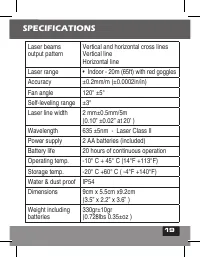
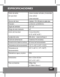
39 Patrón de salidade rayos láser Líneas cruzadas verticales y horizontalesLínea verticalLínea horizontal Alcance del láser Interiores - 20 m (65 pies) con gafas rojas Precisión ±0.2mm/m (±0.0002in/in) Ángulo de ventilador 120° ±5° Rango de auto-nivelación ±3° Ancho de línea láser 2 mm±0.5mm/5m(0.10...
Page 40 - GARANTÍA; CERTIFICADO DE CONFORMIDAD CE
40 GARANTÍA Este producto está cubierto por una garantía limitada de dos años contra defectos de materiales y mano de obra. No cubre los productos que se utilicen inadecuadamente, se modifiquen o se reparen sin la aprobación de Kapro. En caso de problemas con el nivel láser que ha adquirido, por fav...
Page 42 - • Marquage pour l'installation de portes et fenêtre, rails,; REMARQUE
42 Nous vous félicitons pour votre achat du Kapro Prolaser ® Cross 862. Vous êtes en possession de l'un des instruments laser les plus avancés du marché. Ce manuel décrit comment tirer le meilleur parti de votre appareil. APPLICATIONS Le Prolaser ® Cross 862 est un niveau laser avec deux diodes roug...
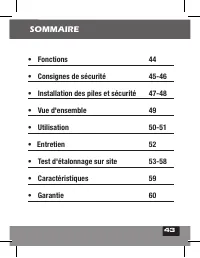
Page 43 - SOMMAIRE
43 • Fonctions 44 • Consignes de sécurité 45-46 • Installation des piles et sécurité 47-48 • Vue d'ensemble 49 • Utilisation 50-51 • Entretien 52 • Test d'étalonnage sur site 53-58 • Caractéristiques 59 • Garantie 60 SOMMAIRE
Page 44 - FONCTIONS; Cet appareil contient des pièces de précision; • Cet instrument laser détermine automatiquement les
44 FONCTIONS REMARQUE Cet appareil contient des pièces de précision sensibles aux chocs externes, aux impacts et à la chute, qui peuvent compromettre ses fonctionnalités - pour conserver sa précision, manipulez-le avec précaution. • Cet instrument laser détermine automatiquement les plans horizontal...
Page 45 - CONSIGNES DE SÉCURITÉ; ATTENTION; • Ne pas placer le faisceau laser de sorte qu'il pointe en; proposition 65 du Code de santé et de sécurité de la Californie).; Les lunettes rouges sont destinées à améliorer
45 CONSIGNES DE SÉCURITÉ ATTENTION Ce produit émet un rayonnement de classe 2 selon la norme EN 60825 -1 Le rayonnement laser peut entraîner de graves lésions oculaires. • Ne pas regarder dans le faisceau laser. • Ne pas placer le faisceau laser de sorte qu'il pointe en direction de vos yeux ou des ...
Page 46 - INSTALLATION DES PILES
46 • Ne pas retirer ou dégrader les étiquettes d'avertissement apposées sur le niveau laser. • Ne pas démonter le niveau laser, le rayonnement laser pouvant gravement endommager l'œil. • Ne pas faire chuter l'appareil. • Ne pas employer de solvant pour nettoyer l'appareil. • Ne pas utiliser à des te...
Page 48 - les piles peuvent se détériorer, fuir ou
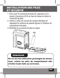
48 ATTENTION: les piles peuvent se détériorer, fuir ou exploser, et causer des blessures ou un incendie.1. Ne pas raccourcir les bornes des piles.2. Ne pas recharger des piles alcalines.3. Ne pas mélanger des piles neuves et anciennes.4. Ne pas jeter les piles aux ordures ménagères.5. Ne pas jeter l...
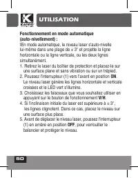
Page 50 - UTILISATION; Fonctionnement en mode automatique; Choisissez les faisceaux que vous souhaitez utiliser en
50 UTILISATION Fonctionnement en mode automatique (auto-nivellement) : IEn mode automatique, le niveau laser s'auto-nivelle lui-même dans une plage de ± 3° et projette la ligne horizontale ou la ligne verticale, ou les deux lignes simultanément. 1. Retirez le laser du boîtier de protection et placez...
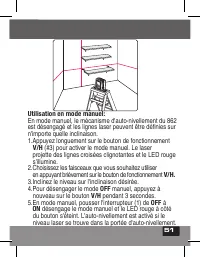
Page 51 - Utilisation en mode manuel:; est désengagé et les lignes laser peuvent être définies sur
51 UTILISATION Utilisation en mode manuel: En mode manuel, le mécanisme d'auto-nivellement du 862 est désengagé et les lignes laser peuvent être définies sur n'importe quelle inclinaison. 1.Appuyez longuement sur le bouton de fonctionnement V/H (#3) pour activer le mode manuel. Le laser projette des...
Page 52 - ENTRETIEN; • Afin de garantir la précision de votre projet,
52 ENTRETIEN • Afin de garantir la précision de votre projet, vérifiezl'exactitude de de votre niveau en procédant aux opérations de vérification de l'étalonnage.• Changez les piles lorsque l'intensité des faisceaux laser faiblit.• Nettoyez la fenêtre de projection et le boîtier du niveau laser à l'...
Page 53 - Le niveau laser quitte l'usine entièrement étalonné. Kapro; Vérification de la précision de hauteur de la ligne; ) Marquez la position du croisement des lignes sur le mur,; TEST D'ÉTALONNAGE SUR SITE
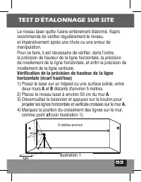
53 ENTRETIEN Le niveau laser quitte l'usine entièrement étalonné. Kapro recommande de vérifier régulièrement le niveau, et impérativement après une chute ou une erreur de manipulation. Pour ce faire, il est nécessaire de vérifier, dans l'ordre, la précision de hauteur de la ligne horizontale, la pré...
Page 54 - ) Marquez sur le mur
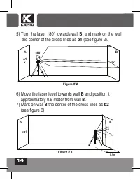
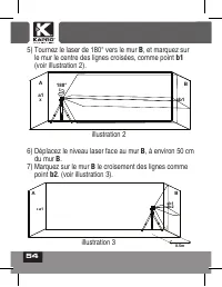
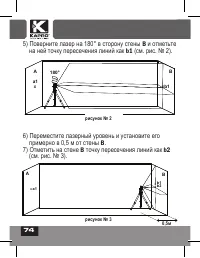
54 5) Tournez le laser de 180° vers le mur B , et marquez sur le mur le centre des lignes croisées, comme point b1 (voir illustration 2). 6) Déplacez le niveau laser face au mur B , à environ 50 cm du mur B . 7) Marquez sur le mur B le croisement des lignes comme point b2 . (voir illustration 3). A ...
Page 55 - Vérification de la précision de nivellement de la ligne
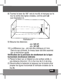
55 5) Tournez le laser de 180° vers le mur B , et marquez sur le mur le centre des lignes croisées, comme point b1 (voir illustration 2). 6) Déplacez le niveau laser face au mur B , à environ 50 cm du mur B . 7) Marquez sur le mur B le croisement des lignes comme point b2 . (voir illustration 3). 8)...
Page 57 - Vérification de la précision de la ligne verticale; ) Une fois le fil à plomb en équilibre, marquez le point
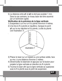
57 5) La distance entre a1 et a2 ne doit pas excéder 1 mm. Dans le cas contraire, le niveau laser doit être examiné par un technicien agréé. Vérification de la précision de la ligne verticale 1) Suspendez à un mur un fil à plomb d'environ 4 mètres. 2) Une fois le fil à plomb en équilibre, marquez le...
Page 58 - verticale et à la même hauteur que
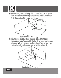
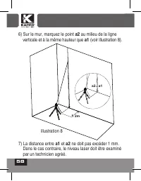
58 6) Sur le mur, marquez le point a2 au milieu de la ligne verticale et à la même hauteur que a1 (voir illustration 8). 7) La distance entre a1 et a2 ne doit pas excéder 1 mm. Dans le cas contraire, le niveau laser doit être examiné par un technicien agréé. a1 X 2m X a2 X Figure # 8 illustration 8
Page 59 - CARACTÉRISTIQUES
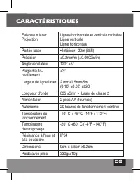
59 Faisceaux laser Projection Lignes horizontale et verticale croisées Ligne verticale Ligne horizontale Portée laser • Intérieur - 20m (65ft) Précision ±0.2mm/m (±0.0002in/in)Angle ventilateur 120° ±5°Plage d'auto- nivellement ±3° Largeur de ligne laser 2 mm±0.5mm/5m (0.10” ±0.02” at 20’ ) Longueur...
Page 60 - GARANTIE; inappropriée, modifiés ou réparés sans l'autorisation de; CERTIFICAT DE CONFORMITÉ CE; électromagnétique (CEM) établi par la directive; DÉCLARATION DE CONFORMITÉ CE; Nous déclarons sous notre responsabilité que le produit:
60 GARANTIE Ce produit est couvert par une garantie limitée de deux ans contre tous défauts de matériel et de fabrication. Cette garantie ne couvre pas les produits utilisés de façon inappropriée, modifiés ou réparés sans l'autorisation de Kapro. En cas de problème avec votre niveau laser, veuillez ...
Page 62 - Сохраните это руководство для последующего
62 Компания Kapro благодарит вас за выбор 862 Prolaser ® Cross. Теперь вам принадлежит один из самых передовых из существующих лазерных инструментов. Это руководство поможет вам эксплуатировать инструмент с максимальной эффективностью. ОБЛАСТИ ПРИМЕНЕНИЯ 862 Prolaser ® оснащён двумя красными лазерны...
Page 63 - СОДЕРЖАНИЕ
63 СОДЕРЖАНИЕ • Функции 64 • Техника безопасности 65-66 • Установка батарей и безопасность 67-68 • Общий вид 69 • Инструкция по эксплуатации 70-71 • Обслуживание 72 • Полевая проверка калибровки 73-78 • Технические характеристики 79 • Гарантия 80
Page 64 - ПРЕДУПРЕЖДЕНИЕ; Этот прибор содержит точные детали чувствительные; ФУНКЦИИ
64 • Этот лазерный инструмент автоматически выравнивается по горизонтальной и вертикальной плоскостям. • Лазерный уровень проецирует перекрещенные горизонтальную и вертикальную линии. • Максимальная рабочая дальность лазера в помещении - 20 м (65ft) (с красными очками) • Автоматическое самовыравнива...
Page 65 - ТЕХНИКА БЕЗОПАСНОСТИ; Этот прибор является источником излучения, которое
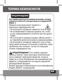
65 ТЕХНИКА БЕЗОПАСНОСТИ ПРЕДУПРЕЖДЕНИЕ Этот прибор является источником излучения, которое относится к Классу II в соответствии со стандартом EN 60825 -1 Лазерное излучение может привести к серьезным повреждениям глаз • Не допускайте попадания лазерного луча в глаза • Не устанавливайте лазерный урове...
Page 67 - УСТАНОВКА БАТАРЕЙ И БЕЗОПАСНОСТЬ; ЗАМЕТКА; Если лазерный уровень
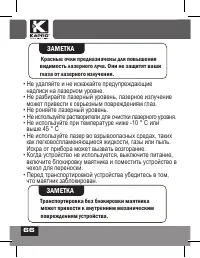
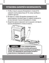
67 AA x 2 • Не удаляйте и не искажайте предупреждающие надписи на лазерном уровне. • Не разбирайте лазерный уровень, лазерное излучение может привести к серьезным повреждениям глаз. • Не роняйте лазерный уровень. • Не используйте растворители для очистки лазерного уровня. • Не используйте при темпер...
Page 68 - ПРЕДУПРЕЖДЕНИЕ:
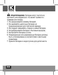
68 ПРЕДУПРЕЖДЕНИЕ: Батареи могут портиться, протекать или вздуваться, что может привести к травмам или пожару. 1. Не закорачивайте клеммы батарей. 2. Не заряжайте щелочные батареи не предназначенные для повторной зарядки. 3 . Не следует смешивать старые и новые батареи. 4. Не выбрасывайте батареи с ...
Page 69 - ОБЩИЙ ВИД; a. Автоматический режим; Крышка батарейного отсека
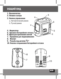
69 ОБЩИЙ ВИД 1. Выключатель 2. Окошко лазера 3. Кнопка управления a. Автоматический режим b. Ручной режим 4. Индикатор 5. Крышка батарейного отсека 6. Щели для крепления лентой 7. Проушина для подвешивания 8. Магнит 9. Резьба под штатив ¼ " 10. Кнопка открывания батарейного отсека
Page 70 - ИНСТРУКЦИЯ ПО ЭКСПЛУАТАЦИИ
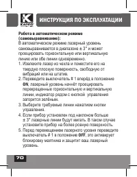
70 Работа в автоматическом режиме (самовыравнивание): В автоматическом режиме лазерный уровень самовыравнивается в диапазоне ± 3° и может проецировать горизонтальную или вертикальную линию или обе линии одновременно. 1. Извлеките лазер из чехла и поместите его на твердую плоскую поверхность, свободн...
Page 71 - Работа в ручном режиме:
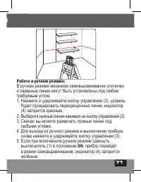
71 ИНСТРУКЦИЯ ПО ЭКСПЛУАТАЦИИ Работа в ручном режиме: В ручном режиме механизм самовыравнивания отключен и лазерные линии могут быть установлены под любом требуемым углом. 1. Нажмите и удерживайте кнопку управления ( 3 ), уровень будет проецировать перекрещенные линии, индикатор (4) загорится красны...
Page 72 - ОБСЛУЖИВАНИЕ
72 ОБСЛУЖИВАНИЕ Для сохранения точности в вашей работе, регулярно проверяйте калибровку вашего лазерного уровня в соответствии с процедурой проверки калибровки в полевых условиях. • Замените батареи, если лазерные лучи начинают тускнеть. • Очищайте окошки лазеров и корпус уровня чистой мягкой тканью...
Page 73 - Проверка калибровки горизонтальной линии по высоте.; ПОЛЕВАЯ ПРОВЕРКА КАЛИБРОВКИ
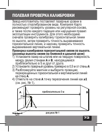
73 ОБСЛУЖИВАНИЕ Завод-изготовитель поставляет лазерные уровни в полностью откалиброванном виде. Компания Kapro рекомендует проверять уровень на регулярной основе, а также после каждого падения или нарушения правил эксплуатации инструмента. Для этого необходимо сначала проверить калибровку горизонтал...
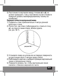
Page 77 - Проверка точности вертикальной линии.
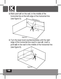
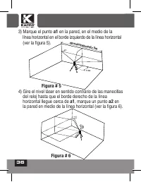
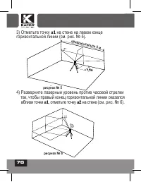
77 3) Отметьте точку a1 на стене на левом конце горизонтальной линии (см. рис. № 5). 4) Разверните лазерный уровень против часовой стрелки так, чтобы правый конец горизонтальной линии оказался вблизи точки a1 , отметьте точку а2 на стене (см. рис. № 6). 5) Расстояние по вертикали между точками a1 и ...
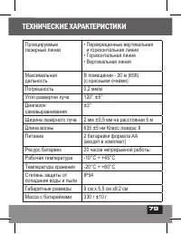
Page 79 - ТЕХНИЧЕСКИЕ ХАРАКТЕРИСТИКИ
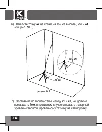
79 6) Отметьте точку а2 на стене на той же высоте, что и a1 . (см. рис. № 8). 7) Расстояние по горизонтали между a1 и a2 , не должно превышать 1мм, в противном случае отправьте лазерный уровень квалифицированному технику на калибровку. ТЕХНИЧЕСКИЕ ХАРАКТЕРИСТИКИ Проецируемые лазерные линии • Перекре...
Page 80 - ГАРАНТИЯ; СЕРТИФИКАТ СООТВЕТСТВИЯ СЕ
80 ГАРАНТИЯ На изделие распространяется двухлетняя гарантия отсутствия дефектов материалов и изготовления. Нарушения правил эксплуатации, изменения конструкции или самостоятельный ремонт приводят к аннулированию гарантии. При появлении проблем с приобретенным лазерным уровнем, верните его в место по...
Page 82 - Rev. 3.0 © 2020 Kapro Industries Ltd.