Page 2 - OPERATION; SAFETY RULES; SAFE OPERATION PRACTICES FOR POWERED WALK-BEHIND ROTARY; TRAINING
2 OPERATION • Do not allow hands, feet, or other body parts or cloth- ing near the rotating tines or any other moving part. The tines begin to rotate once the engine/motor is started and the activating device is engaged. The tines may momentarily rotate after the activating device is released. • Exe...
Page 3 - MAINTENANCE AND STORAGE; WARNING; The engine exhaust from this product con tains
3 • Never pick up or carry a machine while the engine (motor) is running. • Do not operate the tiller while under the influence of alcohol or drugs. • Powered walk-behind tiller work is strenuous. You must be in good physical condition and mentally alert. If you have any condition that might be aggr...
Page 4 - PRODUCT SPECIFICATIONS; CUSTOMER RESPONSIBILITIES; FRANÇAIS; TABLE OF CONTENTS
4 CONGRATULATIONS on your purchase of a new tiller. It has been designed, en gi neered and manu fac tured to give you the best pos sible de penda bil ity and per form ance.Should you experience any prob lems you can not easily remedy, please contact your nearest authorized service center. We have co...
Page 5 - TOOLS REQUIRED FOR ASSEMBLY; CONTENTS OF HARDWARE PACK; ASSEMBLY
5 TOOLS REQUIRED FOR ASSEMBLY A socket wrench set will make assembly easier. Standard wrench sizes are listed.(1) Utility knife(1) Tire pressure gauge(1) Pair of pliers(1) 9/16" wrench OPERATOR’S POSITION (See Fig. 1) When right or left hand is mentioned in this manual, it means when you are in ...
Page 7 - REMOVE TILLER FROM CRATE
7 ASSEMBLY REMOVE TILLER FROM CRATE • Make sure shift lever indicator is in “N” position (See Fig. 6) • Tilt tiller forward by lifting handle. Separate cardboard cover from leveling shield. • Rotate tiller handle to the right and pull tiller out of carton. CONNECT SHIFT ROD (See Fig. 6) • Insert end...
Page 8 - KNOW YOUR TILLER; MEETS ANSI SAFETY REQUIREMENTS
8 KNOW YOUR TILLER READ THIS OWNER'S MANUAL AND SAFETY RULES BEFORE OPERATING YOUR TILLER. Compare the illustrations with your tiller to familiarize yourself with the location of various controls and adjustments. Save this manual for future reference. These symbols may appear on your Tiller or in li...
Page 9 - HOW TO USE YOUR TILLER; TINE OPERATION - WITH WHEEL DRIVE
9 OPERATION HOW TO USE YOUR TILLER Know how to operate all controls before adding fuel and oil or attempting to start engine. STOPPING (See Fig. 8) TINES AND DRIVE • Release tine control to stop movement.• Move shift / emergency disengage lever to “N” (neu- tral) position. ENGINE • Move throttle con...
Page 10 - TO TRANSPORT; TURNING
10 OPERATION TO TRANSPORT CAUTION: Before lifting or trans port- ing, allow tiller engine and muffler to cool. Disconnect spark plug wire. Drain gasoline from fuel tank. AROUND THE YARD • Release the depth stake pin. Move the depth stake down to the top hole for transporting the tiller. Place depth ...
Page 11 - ADD GASOLINE
11 OPERATION TILLING HINTS (See Fig. 14) CAUTION: Until you are accustomed to handling your tiller, start actual field use with throttle in slow position (mid-way between “FAST” and “IDLE”). • Tilling is digging into, turning over, and breaking up packed soil before planting. Loose, unpacked soil he...
Page 12 - CULTIVATING; ADJUST WHEELS FOR CULTIVATING
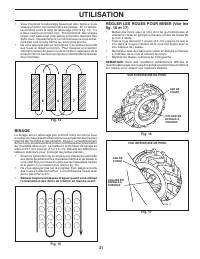
12 • Do not lean on handle. This takes weight off the wheels and reduces traction. To get through a really tough section of sod or hard ground, apply upward pressure on handle or lower the depth stake. Fig. 14 Fig. 15 OPERATION 3 2 1 5 4 6 7 CULTIVATING Cultivating is destroying the weeds between ro...
Page 13 - MAINTENANCE; GENERAL RECOMMENDATIONS; BEFORE EACH USE; LUBRICATION CHART; SERVICE DATES
13 MAINTENANCE GENERAL RECOMMENDATIONS The warranty on this tiller does not cover items that have been subjected to operator abuse or negligence. To receive full value from the warranty, the operator must main tain tiller as instructed in this manual.Some adjustments will need to be made periodicall...
Page 14 - ENGINE; LUBRICATION
14 MAINTENANCE Disconnect spark plug wire before performing any maintenance (except car bu re tor adjustment) to prevent accidental start ing of engine.Prevent fires! Keep the engine free of grass, leaves, spilled oil, or fuel. Re move fuel from tank before tipping unit for maintenance. Clean muffle...
Page 15 - MUFFLER; CLEANING
15 MAINTENANCE MUFFLER Do not operate tiller without muffler. Do not tamper with exhaust system. Damaged mufflers or spark arresters could create a fire hazard. Inspect pe ri odi cally and re place if nec es sary. If your engine is equipped with a spark arrester screen assembly, re move every 50 hou...
Page 16 - SERVICE AND ADJUSTMENTS; TILLER; TIRE CARE; TO AD JUST CARBURETOR
16 SERVICE AND ADJUSTMENTS CAUTION: Disconnect spark plug wire from spark plug and place wire where it cannot come into contact with plug. TILLER TO ADJUST HANDLE HEIGHT (See Fig. 22) Select handle height best suited for your tilling conditions. Handle height will be different when tiller digs into ...
Page 17 - TO REPLACE GROUND DRIVE BELT
17 SERVICE AND ADJUSTMENTS TO REPLACE GROUND DRIVE BELT (See Figs. 24 and 25) • Remove belt guard as described in “TO REMOVE BELT GUARD”. • Remove old belt by slipping off engine pulley first then remove from transmission pulley. • Place new belt in groove of transmission pulley and into engine pull...
Page 18 - TINE REPLACEMENT
18 SERVICE AND ADJUSTMENTS • To maintain the superb tilling performance of this ma chine the tines should be checked for sharpness, wear, and bending, particularly the tines which are next to the transmission. If the gap between the tines ex ceeds 3-1/2" they should be replaced or straight ened ...
Page 19 - STORAGE; ENGINE OIL; OTHER; FUEL SYSTEM
19 STORAGE ENGINE OIL Drain oil (with engine warm) and replace with clean oil. (See “ENGINE” in the Maintenance section of this man ual). CYLINDER(S) • Remove spark plug.• Pour 1 ounce (29 ml) of oil through spark plug hole into cylinder. • Pull starter handle slowly several times to distribute oil....
Page 20 - TROUBLESHOOTING POINTS
20 TROUBLESHOOTING POINTS Will not start 1. Out of fuel. 1. Fill fuel tank. 2. Engine not “CHOKED” properly. 2. See “TO START ENGINE” in Operation section. 3. Engine flooded. 3. Wait several minutes before attempting to start. 4. Dirty air cleaner. 4. Clean or replace air cleaner cartridge. 5. Water...
Page 21 - RÈGLES DE SÉCURITÉ
21 • Ne jamais essayer de faire des réglages pendant que le mo- teur est en marche (sauf là où spécifié par recommandation du fabricant). FONCTIONNEMENT • Ne pas laisser les mains, les pieds, ni d’autres parties du corps ou vêtements à proximité des dents en rotation ou de toute autre pièce en mouve...
Page 22 - ENTRETIEN ET ENTREPOSAGE; AVERTISSEMENT
22 • N’utilisez pas le rotoculteur sous l’influence d’alcool ou de drogues. • Le travail à l’aide d’un rotoculteur à conduite à pied à l’arrière est fatigant. Il faut être en bonne condition physique et mentale. En cas d’interdiction de travaux fatigants pour des questions de santé, consulter un méd...
Page 23 - SOMMAIRE
23 RÈGLES DE SÉCURITÉ.............................. ..........21-22RESPONSABILITÉS DU CLIENT.................................23SPÉCIFICATIONS DE PRODUIT..................................23MONTAGE...............................................................24-26UTILISATION.............................
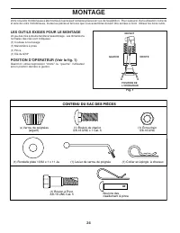
Page 24 - CONTENU DU SAC DES PIÈCES; MONTAGE; LES OUTILS EXIGES POUR LE MONTAGE
24 DEVANT POSITION DE L’OPÉRATEUR DROITE GAUCHE Fig. 1 (1) Collier en épingle à cheveux (1) Boulon de chariot 3/8-16 UNC x 1 Cat. 5 (1) Écrou frein 3/8-16 UNC (1) Levier de verrou de poignée (2) Verrou de poignées (argent) (1) Rondelle plate 13/32 x 1 x 11 Ja. CONTENU DU SAC DES PIÈCES (1) Boulon à ...
Page 25 - INSTALLER LA POIGNEE
25 MONTAGE TIGE DE CHANGEMENT DE VITESSE ENSEMBLE DE LA POIGNÉE Fig. 2 INSTALLER LA POIGNEE (Voir les fig. 3, 4, et 5) • Insérez un verrou de poignée (les dents vers l’extérieur) dans l’encoche de la boîte de vitesse. (Appliquez de la graisse sur le côté lisse du verrou de poignée pour garder le ver...
Page 26 - RACCORDER LA TIGE DE CHANGEMENT DE; HAUTEUR DE POIGNEE
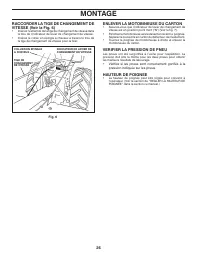
26 MONTAGE RACCORDER LA TIGE DE CHANGEMENT DE VI TES SE (Voir la Fig. 6) • Insérez l’extrémité de la tige de changement de vitesse dans le trou de l’indicateur de levier de changement de vitesse. • Insérez le collier en épingle à cheveux à travers le trou de la tige de changement de vitesse pour la ...
Page 27 - UTILISATION; CONNAISSEZ VOTRE MOTOBINEUSE
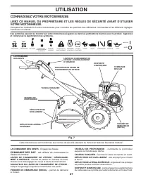
27 UTILISATION Fig. 7 LA COMMANDE DES DENTS - Engage des fraises. COMMANDE DES GAZ - est utilisée de commander la vitesse de moteur. LEVIER DE CHANGEMENT DE VITESSE / DÉSENGAGE- MENT D’URGENCE - Permet de passer les vitesses de trans- mission et de désengager les roues et dents d’entraînement. INDIC...
Page 28 - COMMENT UTILISER VOTRE MOTO-; MARCHE AVANT - ROUES SEULEMENT LES
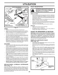
28 UTILISATION LABOURAGE LE MOINS PROFOND (BINAGE) POSITION DE TRANSPORT LABOURAGE LE PLUS PROFOND JAUGE DE PROFONDEUR Fig. 9 JAUGE DE PROFONDEUR (Voir la fig. 9) Le jauge de profondeur peut être soulevé ou baissé pour vous donner le labourage et le binage aux usages variés ou pour le transport faci...
Page 29 - VIRER; AVANT DE DÉMARRER LE MOTEUR; REMPLIR LE MOTEUR D’HUILE
29 UTILISATION Fig. 12 VIRER • Relâchez la barre de commande d’entraînement.• Déplacez la commande des gaz à la position lente (“SLOW”). • Mettez l’indicateur de levier de changement de vitesse à la position de devant (“F”). Les fraises ne tourneront pas. • Soulevez la poignée pour élever les fraise...
Page 30 - CONSEILS DE LABOURAGE
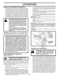
30 UTILISATION CONSEILS DE LABOURAGE ATTENTION: Utilisez la motobineuse avec la commande des gaz à la position lente “SLOW” (à mi-chemin entre les positions rapide “FAST” et ralenti “IDLE” ) jusqu’à ce que vous soyez habitué à elle. • Le labourage est le creusage en retournant et en ameu blis sant l...
Page 31 - BINAGE; RÉGLER LES ROUES POUR BINER (Voir les
31 UTILISATION Fig. 15 Fig. 14 3 2 1 5 4 6 7 BINAGE Le binage est un labourage peu profond entre les sillons pour arracher les mauvaises herbes et pour les empêcher de priver les plantes de l’humidité et des aliments. De plus, l’ameublissement de la couche supérieure de la croûte con tri bue ra à la...
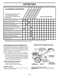
Page 32 - ENTRETIEN; CALENDRIER D’ENTRETIEN; DATES D’ENTRETIEN; TABLEAU DE LUBRIFICATION; AVANT CHAQUE UTILISATION
32 ENTRETIEN CALENDRIER D’ENTRETIEN INSCRIVEZ LES DATES AU FUR ET À MESURE QUE VOUS EFFECTUEZ LES ENTRETIENS RÉGULIERS Vérifiez le niveau d’huile de moteur Changez l’huile de moteur Huilez les points de pivotement Inspectez le tamis à air Inspectez le silencieux pare-étincelles Nettoyez/remplacez la...
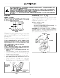
Page 33 - LUBRIFICATION
33 ENTRETIEN Débranchez le fil de bougie d'allumage avant d'effectuer tout entretien (sauf le réglage du carburateur) pour éviter un démarrage accidentel du moteur.Évitez les incendies! Maintenez le moteur exempt d'herbe, de feuilles et d'huile ou de carburant répandu. Vidangez le carburant du réser...
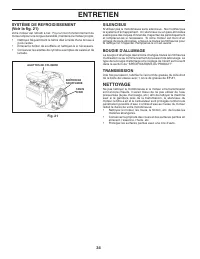
Page 34 - SYSTÈME DE REFROIDISSEMENT; NETTOYAGE
34 ENTRETIEN SYSTÈME DE REFROIDISSEMENT (Voir la fig. 21) Votre moteur est refroidi à l'air. Pour un bon fonctionnement du moteur et pour une longue durabilité, maintenez le moteur propre.• Nettoyez fréquemment le tamis d'air à l'aide d'une brosse à poils raides. • Enlevez le boîtier de soufflerie e...
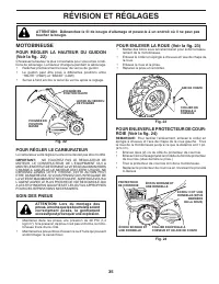
Page 35 - SOIN DES PNEUS; RÉVISION ET RÉGLAGES; POUR ENLEVER LE PROTECTEUR DE COUR-; MOTOBINEUSE; POUR RÉGLER LA HAUTEUR DU GUIDON
35 SOIN DES PNEUS ATTENTION: Lors du montage des pneus, à moins que les bourrelets soient cor rec te ment posés, le gonflement excessif peut provoquer une ex plo sion. • Maintenez dans les pneus une pression de 20 PSI (1,4 kg/cm 2 ). Si la pression de pneu n’est pas uniforme, la moto- bineuse tirera...
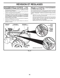
Page 36 - POUR REMPLACER LA COURROIE D ’ E N -
36 RÉVISION ET RÉGLAGES POUR REMPLACER LA COURROIE D ’ E N - TRAÎNEMENT À TERRE (Voir les fig. 24 et 25) • Enlevez le protecteur de courroie (Voir “ENLEVER LE PRO- TEC TEUR DE COURROIE”). • Enlevez la vieille courroie en la glissant de la poulie du moteur et de la poulie de tranmission. • Posez la n...
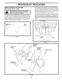
Page 37 - REMPLACEMENT DES FRAISES
37 RÉVISION ET RÉGLAGES Fig. 28 NOU VEL LE DENT DENT USÉE Fig. 26 TRANSMISSION DENT DENT 3-1/2" MAX (9 CM) Fig. 27 COLLIER EN ÉPINGLE À CHEVEUX BOULON DE CISAILLEMENT BOULON DE CISAILLEMENT COLLIER EN ÉPINGLE À CHEVEUX BORD TRAN CHANT BORD TRAN- CHANT BORD TRAN- CHANT REMPLACEMENT DES FRAISES (V...
Page 38 - ENTREPOSAGE; SYSTÈME D'ALIMENTATION; INFORMATION SUPPLEMENTAIRE
38 ENTREPOSAGE Préparez immédiatement votre motobineuse pour l’en tre po sa ge à la fin de la saison ou si l'unité ne sera pas utilisée pendant 30 jours ou plus. AVERTISSEMENT: N’entreposez jamais la motobineuse lorsque le ré ser voir contient d’essence dans un bâtiment où les va peurs pour raient p...
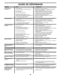
Page 39 - GUIDE DE DÉPANNAGE
39 GUIDE DE DÉPANNAGE Le moteur refuse 1. Sans d’essence. 1. Remplissez le réservoir d’essence. de démarrer 2. Le moteur n’est pas correctement étranglé. 2. Référez-vous à la section de “DÉMARRER LE MOTEUR” dans la section d’utilisation. 3. Le moteur est noyé. 3. Attendez quelques miÉcroues avant de...


 Husqvarna DC5500 Manual
 Husqvarna DM 340 Manual
 Husqvarna dm 406 h Manual
 Husqvarna DRT 900 Manual
 Husqvarna DRT900 Manual
 Husqvarna DRT900E Manual
 Husqvarna DS70 Manual
 Husqvarna DT22 Manual
 Husqvarna DT22B5DSA Manual
 Husqvarna E10 Manual