Frigidaire FPEC3677RF - User Manual
Frigidaire FPEC3677RF Hob – User Manual, read for free online in PDF format. We hope this helps you resolve any issues you may have. If you have further questions, please contact us through the contact form.


Table of Contents:
- Page 2 – ELECTRIC COOKTOP INSTALLATION INSTRUCTIONS; Figure 2 – COUNTERTOP CUTOUT OPENING; fire by reaching over heated surfaces, cabinet; Important Notes to the Installer; cooktop, allow Dimension
- Page 3 – the box and the appliance, so it can be moved if; Unpacking Instructions; Provide Electrical Connection; Volt, 60 Hz AC only electrical supply is required on a; Electrical Connection
- Page 4 – ‐WIRE GROUNDED JUNCTION BOX; supplied with the appliance are UL-recognized for; RISK OF ELECTRIC SHOCK:
- Page 5 – Figure 7
- Page 6 – Cooktop Installation; Do not use caulking compound cooktop should
- Page 7 – Coil Elements; Checking Operation; Model and Serial Number Location
- Page 8 – installed on two runners,; WITH AN ELECTRIC COOKTOP MOUNTED ABOVE
- Page 9 – INSTRUCCIONES PARA LA INSTALACION DE LA ESTUFA ELECTRICA; Canadá
- Page 10 – Para evitar riesgos; Figura 2 – EL CORTE DE LA PARTE SUPERIOR DEL ARMARIO; Notas importantes para el instalador; Lea todas las instrucciones contenidas en este manual; Nota importante al consumidor
- Page 11 – Instrucciones de desembalaje; INSTRUCCIONES; Asegúrese de que su estufa sea instalada y puesta; Provea conexión eléctrica; El amperaje del disyuntor o del fusible; Conexión eléctrica; El usuario tiene la responsabilidad personal y obligación; Figura 3; Placa con los numeros de modelo
- Page 12 – el
- Page 14 – No utilice compuesto de retaque la estufa; Instalación de la estufa; Verifique además que todos los tornillos de la estufa
- Page 15 – con espirales; Revisión de operación
- Page 16 – INSTALACIÓN TÍPICA DEBAJO DE LA MESADA DE HORNO SIMPLE EMPOTRADO; la cocina donde están detalladas las dimensiones).; ón; DIMENSIONES DE ABERTURA
- Page 17 – INSTRUCTIONS D'INSTALLATION POUR PLAQUE DE CUISSON ÉLECTRIQUE; Dimensions de la plaque de cuisson; INSTRUCTIONS DE SÉCURITÉ IMPORTANTES; Figure 1; UN INSTALLATEUR QUALIFIÉ DOIT EFFECTUER; POUR VOTRE SÉCURITÉ: N’entreposez et n’utilisez pas; Canada
- Page 18 – Figure 2 – OUVERTURE DU DÉCOUPAGE DE DESSUS DU COMPTOIR; Installateur
- Page 19 – DIRECTIVES IMPORTANTES; Connexion électrique; Observez tous les règlements et les codes locaux; Instructions de déballage; Connexions électriques; Risque de choc électrique (Si
- Page 20 – BOÎTE DE JONCTION A 3 FILS ‐MISE A LA TERRE; La mise à la terre de cet appareil est obligatoire.; Cet appareil est fabriqué avec un câble d’alimentation; NE PAS utiliser un tuyau à gaz; être de 150V ou moins.
- Page 21 – Figure 7 ‐; Si l’appareil est utilisé dans une maison; Figure 6 –; BOÎTE DE JONCTION À 4 FILS
- Page 22 – N’utilisez pas de pâte à calfeutrage on doit pou; Installation de la plaque de cuisson; Vérifiez si la plaque de cuisson est endommagée. Veillez; Figure 8; Vis; conformément aux codes locaux ou, en leur absence,
- Page 23 – avec éléments spiraux:; Vérification de fonctionnement; Emplacement des numéros de modèle et de; Vous sauverez probablement du temps et de l’argent.
- Page 24 – te de jonction pour; INSTALLATION TYPIQUE D'UN FOUR ENCASTRÉ SIMPLE SOUS LE COMPTOIR; Voir; DIMENSIONS DE L'OUVERTURE
1
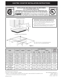
ELECTRIC COOKTOP INSTALLATION INSTRUCTIONS
A
F
B
C
D
E
All dimensions are in inches (cm).
Only some models are available in Canada.
*
Allow 2" (5 cm) space below cooktop to clear the electric cable and allow for installation of the
junction box on the wall at the back of the cooktop.
P/N 318205403 (0904) Rev. C
English – pages 1-8
Español – pages 9-16
Français – pages 17-24
Cooktop Dimensions
IMPORTANT INSTALLATION‑INFORMATION
• All electric cooktops run off a single phase, three-wire
or four-wire cable, 240/208 volt, 60 hertz, AC only
electrical supply with ground.
• Please note minimum distances between cooktop and
adjacent and overhead cabinetry is 30" (76.2cm).
* 30" (76.2 cm) min. for unprotected cabinet
24" (61 cm) min. for protected surface
Cooktop Cutout Dimensions
Figure 1
30" Min. *
(76.2 cm)
Printed in China
MODEL
A. LENGTH
B. WIDTH
C. DEPTH
CUTOUT DIMENSIONS
F. DEPTH
BELOW
COOKTOP*
D. LENGTH
E. WIDTH
MIN.
MAX.
MIN.
MAX.
26" Coil Elements
25¾ (65.4)
21
9
/
16
(54.8)
3½ (8.9)
25 (63.5)
25 (63.5)
20½ (52.1) 20½ (52.1)
5½ (14)
30" Ceramic Glass
30
3
/
8
(77.8)
21
3
/
8
(54.4)
2
5
/
8
(6.7)
29
5
/
8
(75.2) 29
7
/
8
(75.9) 20¼ (51.4) 20½ (52.1)
5 (12.7)
30" Coil Elements
30 (76.2)
21½ (54.6)
3 (7.6)
26¾ (67.9) 28¼ (71.8) 19
1
/
8
(48.6)
20 (50.8)
5 (12.7)
32" Ceramic Glass
32¼ (81.9)
20¼ (51.4)
3¾ (9.5)
31 (78.7)
31¼ (79.4)
19 (48.3)
19¼ (48.9)
5¾ (14.6)
24 (61.0)
23 (58.5)
23¼ (59.0)
36" Ceramic Glass
36¾ (93.5)
21
3
/
8
(54.4)
2
5
/
8
(6.7)
35
5
/
8
(90.5) 36
1
/
8
(91.8) 20¼ (51.4) 20½ (52.1)
5 (12.7)
36" Coil Elements
(36" X 18")
36 (91.4)
18 (45.7)
3
7
/
8
(9.8)
34¼ (87)
34
3
/
8
(87.3) 16
5
/
8
(42.2) 16¾ (42.5)
5
7
/
8
(14.9)
36" Coil Elements
(36" x 21½")
36 (91.4)
21½ (54.6)
3 (7.6)
32¾ (83.2)
34¼ (87)
19 (48.3)
20 (50.8)
5 (12.7)
INSTALLATION AND SERVICE MUST BE PERFORMED
BY A QUALIFIED INSTALLER.
IMPORTANT: SAVE FOR LOCAL ELECTRICAL INSPECTOR’S USE.
READ AND SAVE THESE INSTRUCTIONS FOR FUTURE REFERENCE.
WARNING
FOR YOUR SAFETY: Do not store or use gasoline or other
flammable vapors and liquids in the vicinity of this or any other appliance.
Canada
United States
32" Coil Elements
32¼ (81.9)
20¼ (51.4)
3¾ (9.5)
31 (78.7)
31¼ (79.4)
19 (48.3)
19¼ (48.9)
5¾ (14.6)
24" Ceramic Glass
21
3
/
8
(54.4)
2
5
/
8
(6.7)
20¼ (51.4) 20½ (52.1)
5 (12.7)
"Loading the manual" means you need to wait until the file loads and becomes available for online reading. Some manuals are very large, and the time they take to appear depends on your internet speed.
Summary
2 ELECTRIC COOKTOP INSTALLATION INSTRUCTIONS F E D A Figure 2 – COUNTERTOP CUTOUT OPENING CAUTION To eliminate the risk of burns or fire by reaching over heated surfaces, cabinet storage space located above the cooktop should be avoided. If cabinet storage is provided, risk can be reduced by install...
3 ELECTRIC COOKTOP INSTALLATION INSTRUCTIONS 2. The flexible armored cable extending from the appliance should be connected directly to the junction box. The junction box should be located as shown in Figure 1 or Figure 2 and with as much slack as possible remaining in the cable between the box and ...
4 ELECTRIC COOKTOP INSTALLATION INSTRUCTIONS Figure 5 – U.S.A. Only 3‑WIRE GROUNDED JUNCTION BOX Cable from Power Supply Black Wires Junction Box Cable from appliance Ground Wire (Bare or Green Wire) Ground Wire White Wire Red Wires U.L.-Listed Conduit Connector (or CSA listed) Figure 4 – U.S.A. Onl...