Page 2 - Contents
1. Before You Start... 1 Installation and Maintenance 1 Peculiar Smells 1 If You Smell Gas 1 Ventilation 1 Personal Safety 1 Cleaning 2 2. Cooker Overview 3 Hotplate Burners 3 The Wok Cradle (optional) 5 The Griddle (optional) 5 The Grill / Glide-out Grill 6 The Ovens 7 The Clocks 8 Accessories 12 M...
Page 3 - Ventilation; If You Smell Gas
1 This User Guide covers a number of different models. Although some of the illustrations will look different to your particular model the functions will be the same. We hope the meaning is clear.Your cooker should give you many years of trouble-free cooking if installed and operated correctly. It i...
Page 4 - Cleaning
2 Cooking high moisture content foods can create a ‘steam burst’ when an oven door is opened. When opening the oven stand well back and allow any steam to disperse. ArtNo.324-0001 Steam burst n n Always keep combustible materials, e.g. curtains, and flammable liquids a safe distance away from your c...
Page 5 - Hotplate Burners; made at every burner – this is normal. Do not attempt to
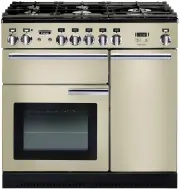
3 ArtNo.270-0001 Proplus control to high 2. Cooker Overview The 90 dual fuel cooker (Fig.2-1) has the following features:A. 5 hotplate burners including a wok burnerB. A control panel C. A glide-out grill D. Programmable main fan ovenE. Tall fan oven Hotplate Burners The drawing by each of the centr...
Page 6 - Wok Burner
4 ArtNo.311-0002 Pan with rim If, when you let go of the control knob, the burner goes out, then the FSD has not been bypassed. Turn the control knob to the OFF position and wait for one minute before you try again, this time making sure to hold in the control knob for slightly longer.Adjust the fla...
Page 7 - DO NOT put it crossways – it will not fit properly and
5 ArtNo.090-0002 90 Griddle position ArtNo.090-0004 Incorrect griddle position ArtNo.311-0006 Correct wok sizes The Wok Cradle (optional) The wok cradle is designed to fit a 35 cm wok. If you use a different wok, make sure that it fits the cradle. Woks vary very widely in size and shape. It is impor...
Page 9 - The Ovens; The clock must be set to the time of day before the left-; hand oven will work. See the following section on ‘The; Operating the Ovens
7 The Ovens The clock must be set to the time of day before the left- hand oven will work. See the following section on ‘The Clock’ for instructions on setting the time of day.References to ‘left-hand’ and ‘right-hand’ ovens apply as viewed from the front of the appliance.Both ovens are fan ovens th...
Page 10 - The Clocks; The cooker will not operate unless the clock
8 The Clocks You can use the timer (Fig.2-21) to turn the left-hand oven on and off. The clock must be set to the time of day before the ovens will work. The 2-Button Clock (Professional+) Setting the Time of DayWhen the clock is first connected, the display flashes ( 0.00 ) and ( ) alternately. T...
Page 11 - You cannot set a start time directly – this is set; automatically by a combination of the ‘cook time’ and
9 To Start and Stop the Programmable Oven Using the TimerBefore you set the clock, decide on both the ‘cook time’ and the ‘stop time’ . You cannot set a start time directly – this is set automatically by a combination of the ‘cook time’ and ‘stop time’.Turn the Timer knob to the [ ] position (Fig....
Page 12 - Note: You cannot set a start time directly – this is set; A B C D E F
10 The 6-button Clock (Kitchener) Setting the Time of DayThe 6-button LCD clock is shown in Fig.2-34. When the clock is first connected the display flashes ( 0.00 ) and ( ) alternately.Press and hold both the [ ] and [ ] buttons down (Fig.2-35). Now press the [+] button (or the [–] button) unt...
Page 13 - Make sure that the clock is in manual mode and cancel; To Turn Off the Key Lock
11 AUTO is Showing, You Want to Reset to Manual CookingTo return to manual cooking from any automatic setting, the ‘cook period’ must be cancelled. Press and hold the [ ] button and then press the [ –] button until the display reads ( 0.00 ). Press the [ ] button to return to manual cooking. Key...
Page 14 - ‘Troubleshooting’
12 Accessories Oven Shelves – Left-hand (Main) Oven In addition to the flat shelves, some models are supplied with a drop shelf (Fig.2-49). The drop shelf increases the possibilities for oven shelf spacing.The oven shelves can be easily removed and refitted.Pull the shelf forward until the back of t...
Page 15 - ‘Cleaning Your
3. Cooking Tips Tips on Cooking with the Timer If you want to cook more than one dish, choose dishes that require approximately the same cooking time. However, dishes can be ‘slowed down’ slightly by using small containers and covering them with aluminium foil, or ‘speeded up’ slightly by cooking sm...
Page 17 - Cleaning Your Cooker; Essential Information; NEVER use paint solvents, washing soda, caustic; The Single Ring Burners
15 5. Cleaning Your Cooker Essential Information Isolate the electricity supply before carrying out any thorough cleaning. Allow the cooker to cool. n n NEVER use paint solvents, washing soda, caustic cleaners, biological powders, bleach, chlorine based bleach cleaners, coarse abrasives or salt. n n...
Page 18 - Grills; make sure that they are cool, or use oven gloves.; Cleaning the Glide-out Grill; DO NOT put the side runners in a dishwasher.; Control Panel and Doors
16 ArtNo.331-0001Grill pan pulled forwards Fig.5-5 ArtNo.331-0003 Grill frame out, no pan ArtNo.331-0004 Removing the grill frame Fig.5-6 Fig.5-7 ArtNo.331-0005 Removing the grill rail Fig.5-8 Grills The grill pan and trivet should be washed in hot soapy water. Alternatively, the grill pan can be wa...
Page 19 - Glass Fronted Door Panels; ‘Moving the Cooker’; DO NOT use harsh abrasive cleaners or sharp metal; Ovens; materials that will scratch the surface.; The Tall Oven
17 Glass Fronted Door Panels The oven door front panels can be taken off so that the glass panels can be cleaned. Move the cooker forward to gain access to the sides (see the ‘Moving the Cooker’ section under ‘Installation’ ). Open the oven door slightly and remove the front panel fixing screws from...
Page 20 - Cleaning Table; Cleaners listed (Table 5-1) are available from supermarkets or; up any spillages immediately.; Hotplate
18 Cleaning Table Cleaners listed (Table 5-1) are available from supermarkets or electrical retailers as stated. For enamelled surfaces use a cleaner that is approved for use on vitreous enamel.Regular cleaning is recommended. For easier cleaning, wipe up any spillages immediately. Hotplate Part Fin...
Page 23 - INSTALLATION; Service and Spares; * This information is on the appliance data badge.; If You Have a Problem; re-conditioned or unauthorised controls. Contact your retailer.
INSTALLATION Check the appliance is electrically safe and gas sound when you have finished. 21 7. Installation Service and Spares Firstly, please complete the appliance details below and keep them safe for future reference – this information will enable us to accurately identify the particular appli...
Page 24 - Dear Installer; Installer’s Name
INSTALLATION Check the appliance is electrically safe and gas sound when you have finished. 22 Dear Installer Before you start your installation, please complete the details below, so that, if your customer has a problem relating to your installation, they will be able to contact you easily. You mus...
Page 25 - You will need the following equipment to complete the
INSTALLATION Check the appliance is electrically safe and gas sound when you have finished. 23 Checking the Parts: You will need the following equipment to complete the cooker installation satisfactorily: • Flexible gas hose. • Gas pressure tester/manometer. • Multimeter: For electrical checks. You ...
Page 26 - Positioning the Cooker; Overhead – Measurement A; *The fixing of 5 mm thick ceramic tiles to the surface, or; Moving the Cooker; On no account try and move the cooker while it is
INSTALLATION Check the appliance is electrically safe and gas sound when you have finished. 24 Fig.7-3 ArtNo.091-0004 - 90DF - cooker clearances (AUS) B C D E A Positioning the Cooker The diagram (Fig.7-1) shows the minimum recommended distance from the cooker to nearby surfaces as given in AS 5601....
Page 27 - Lowering the Two Rear Rollers; Completing the Move; nn; DO NOT use the door handles or control knobs to; Levelling the Cooker; A stability bracket and chain MUST be fitted when; Fitting a Stability Bracket
INSTALLATION Check the appliance is electrically safe and gas sound when you have finished. 25 Lowering the Two Rear Rollers To lower the rear rollers, first fit a 13 mm spanner or socket wrench onto the hexagonal adjusting nut at the front of the cooker (Fig.7-4). Rotate the nut – clockwise to rais...
Page 28 - Fitting the Restraining Chain; Gas Connection; Natural Gas; Conversion to Propane Gas; Pressure Testing
INSTALLATION Check the appliance is electrically safe and gas sound when you have finished. 26 ArtAUS.141-0007 - Gas connections - 90 Elan 300 100 240 A 100 All dimensions in millimetres Gas inlet Fig.7-10 Fitting the Restraining Chain The restraining chain MUST be fitted.The length of chain between...
Page 29 - Electrical Connection; Fixed Wiring
INSTALLATION Check the appliance is electrically safe and gas sound when you have finished. 27 ArtNo.132-0001 - 1 phase 240Vac 50Hz 1-phase 230 V AC 50 Hz Fig.7-11 Fig.7-12 Electrical Connection This appliance must be installed by a qualified electrician to comply with the relevant regulations (AS/N...
Page 30 - Final Checks; Note: The clock must be set before the ovens will work. See; The Clock; Hotplate Check; Final Fitting; Fitting the 1-piece Plinth; Customer Care; Installer: Please complete your details in this Guide, inform
INSTALLATION Check the appliance is electrically safe and gas sound when you have finished. 28 Final Checks Note: The clock must be set before the ovens will work. See ‘ The Clock ’ section for instructions on setting the time of day. Hotplate Check Check each burner in turn. There is a Flame Superv...
Page 31 - WARNING – SERVICING TO BE CARRIED OUT ONLY BY AN AUTHORISED PERSON; Injectors; Tap Adjustment; ‘Technical Data’; Conversion to Propane Gas
WARNING – SERVICING TO BE CARRIED OUT ONLY BY AN AUTHORISED PERSON Disconnect from electricity and gas before servicing. Check appliance is safe when you have finished. 29 Conversion from Natural Gas (1.0 kPa) to LPG X Propane (2.54 kPa) n n This conversion must be performed by a competent person, i...
Page 32 - Set the Governor; Make sure that the appliance is gas sound.; Affix Label
WARNING – SERVICING TO BE CARRIED OUT ONLY BY AN AUTHORISED PERSON Disconnect from electricity and gas before servicing. Check appliance is safe when you have finished. 30 Set the Governor Unscrew the governor’s brass top. In the base of the brass top is a plastic snap-in converter device (Fig.8-4)....
Page 33 - Panels; To Remove the Control Panel; the top by 2 holes in the top edge, one at each end, that; To Remove the Side Panels; forward. Remove the 4 retaining screws for each panel
WARNING – SERVICING TO BE CARRIED OUT ONLY BY AN AUTHORISED PERSON Disconnect from electricity before servicing. Check appliance is safe when you have finished. 31 ArtNo.090-0021 Hotplate removal 9. Servicing n n BEFORE SERVICING ANY GAS CARRYING COMPONENTS TURN OFF THE GAS SUPPLY n n Check the appl...
Page 34 - Hotplate; Make sure you replace the rear earthing; Right-hand Wok Burner; Control Panel
WARNING – SERVICING TO BE CARRIED OUT ONLY BY AN AUTHORISED PERSON Disconnect from electricity before servicing. Check appliance is safe when you have finished. 32 2 Hotplate 2.1 To Remove the Hotplate DISCONNECT FROM THE ELECTRICITY SUPPLY.Remove the pan supports and burner heads. Remove the screws...
Page 35 - Grill; To Replace the Grill Controller; DISCONNECT FROM THE ELECTRICITY SUPPLY.; To Replace the Grill Element; Ovens; To Remove the Oven Inner Back; Main Oven; To Change the Oven Fan
WARNING – SERVICING TO BE CARRIED OUT ONLY BY AN AUTHORISED PERSON Disconnect from electricity before servicing. Check appliance is safe when you have finished. 33 4 Grill 4.1 To Replace the Grill Controller DISCONNECT FROM THE ELECTRICITY SUPPLY. n n BEFORE SERVICING ANY GAS CARRYING COMPONENTS, TU...
Page 36 - To Replace an Oven Element
WARNING – SERVICING TO BE CARRIED OUT ONLY BY AN AUTHORISED PERSON Disconnect from electricity before servicing. Check appliance is safe when you have finished. 34 Element fixing screws ArtNo.321-0005 Fan oven element retaining nuts and washers (3 off each) and lift the fan away from the rear of the ...
Page 37 - Doors
WARNING – SERVICING TO BE CARRIED OUT ONLY BY AN AUTHORISED PERSON Disconnect from electricity before servicing. Check appliance is safe when you have finished. 35 ArtNo.320-0003 Oven door latch B ArtNo.320-0004 Oven door keep ArtNo.320-0002a Proplus oven door side screws ArtNo.320-0006 Oven door hi...
Page 38 - To Remove the Tall Oven Door
WARNING – SERVICING TO BE CARRIED OUT ONLY BY AN AUTHORISED PERSON Disconnect from electricity before servicing. Check appliance is safe when you have finished. 36 6.7 To Remove the Tall Oven Door Open the oven door. Supporting the door, remove the 2 screws securing the upper hinge and packing to th...
Page 40 - Connection & Test Pressures; See the appliance badge for test pressures.; Dimensions; Refer to ‘; Ratings; Gas burner inputs based on Gross Calorific Value.; Oven Efficiency; Large
38 11. Technical Data This cooker is designed for use on Natural Gas, although a conversion for LP (LPG X Propane (2.54 kPa)) gas is packed with the cooker.INSTALLER: Please leave these instructions with the user.DATA BADGE LOCATION: Cooker back. The serial number is repeated on the badge below the ...
Page 41 - Notes