Page 3 - Contents
i 1. Before You Start... 1 Personal Safety 1 Electrical Connection Safety 2 Peculiar Smells 3 Ventilation 3Maintenance 3Induction care 4 Grill/Glide-out Grill™ Care 7 Cooling Fan 7 Cooker Care 7 Cleaning 8 2. Cooker Overview 9 The Hob 9 Pan Detector, 10 Residual Heat Indicator, H 11 Child Lock, 11 L...
Page 4 - ii
Page 5 - Personal Safety
1 Your cooker should give you many years of trouble-free cooking if installed and operated correctly. It is important that you read this section before you start. Personal Safety This appliance is for cooking purposes only. It must not be used for other purposes, for example heating a room. Using it...
Page 6 - Electrical Connection Safety; THE APPLIANCE MUST BE
2 ArtNo.132-0001 - 1 phase 240Vac 50Hz 1-phase 230 V AC 50 Hz Electrical Connection Safety n WARNING: THE APPLIANCE MUST BE EARTHED. The cooker is preset for a single-phase earthed electrical connection. It is essential to install a multi-pole circuit breaker that completely disconnects the applianc...
Page 8 - Induction care; IMPORTANT INFORMATION FOR
4 Induction care • IMPORTANT INFORMATION FOR PACEMAKER AND IMPLANTED INSULIN PUMP USERS: The functions of this hob comply with the applicable European standards on electromagnetic interference. If you are fitted with a pacemaker or implanted insulin pump and are concerned please consult your doctor ...
Page 10 - Oven Care; OFF
6 • We recommend that you avoid wiping any surface unit areas until they have cooled and the indicator light has gone off. Sugar spills are the exception to this (see ‘Cleaning your Cooker’). After cleaning, use a dry cloth or paper towel to remove any cleaning cream residue. • The ceramic surface s...
Page 11 - Oven Shelves; Hob Care
7 • Make sure the shelves are pushed firmly to the back of the oven. DO NOT close the door against the oven shelves. • DO NOT use aluminium foil to cover shelves, linings or the oven roof. • When the oven is on, DO NOT leave the oven door open for longer than necessary, otherwise the control knobs m...
Page 12 - Cleaning
8 Cleaning • Isolate the electricity supply before carrying out any thorough cleaning. Allow the cooker to cool. • In the interests of hygiene and safety, the cooker should be kept clean at all times as a build up in fats and other food stuff could result in a fire. • Clean only the parts listed in ...
Page 13 - The Hob
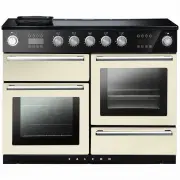
9 Your 110 induction cooker ( Fig. 2.1 ) has the following features: A. 5 induction cooking zones B. Control panel C. Glide-out grill with 4 position trivet D. Multifunction oven E. Steam cavity F. Bread Proving/Storage Drawer The Hob Use only pans that are suitable for induction hobs. We recommend ...
Page 18 - TOP TIPS; Bread Proving Drawer; NOTE
14 F TOP TIPS Not sure of the capacity of your loaf tins? • A one pound loaf tin will hold 800ml of water • A two pound loaf tin will hold 1.5 litres of water. • Cover the dough while it is proving with greased cling film, be careful not to anchor the cling film too tightly so that it prevents the d...
Page 19 - The Handyrack
15 Telescopic shelf - Left-hand (Main) Oven As well as standard shelves, the left-hand oven is supplied with a set of runners for a glide-out oven shelf. To fit the glide-out shelf, hook the front of the shelf onto the runners as shown ( Fig. 2.17 ). The rear of the shelf should rest on the runners,...
Page 20 - Four grill height positions; To switch on both elements
16 Nearest to the element Middle High Middle Low Furthest from the element 3. Using the Glide-out Grill™ 180o 180o 180o 180o Nearest to the element Middle Low Middle High Furthest from the element Four grill height positions Four grill height positions refer to Fig. 3.5 To switch on both elements Fi...
Page 21 - The Multifunction Oven; To select a cooking function
17 4. The Multifunction Oven The clock must be set to the time of day before the oven will work. See the section on ‘The Clock’ for instructions on setting the time of day. References to ‘left-hand’ and ‘right-hand’ ovens apply as viewed from the front of the appliance. The left-hand oven is a multi...
Page 22 - Rapid heat mode can only be activated when the Fan; Oven Lights; Display Lock
18 ECO Mode This setting saves energy, cooking in fanned mode, for foods requiring a cooking time of 45 minutes or less. No preheating . Note: The oven door must remain closed during ECO mode. Failure to do so will result in the oven continuing to cook after the pre-set 45 minutes.The following food...
Page 23 - Accessories; Glide-out Oven Shelves; To remove the glide-out shelf; Steam cavity Shelves
19 Front Accessories Glide-out Oven Shelves The left-hand oven is supplied with 2 glide-out oven shelves.To fit the glide-out shelf, hook the front of the shelf onto the runners as shown ( Fig. 4.3 ). The rear of the shelf should rest on the runners, in front of the rear stop ( Fig. 4.3 ). The glide...
Page 24 - The clock must be set to the time of day before the multi-
20 ArtNo.320-0015 Fitting the Handyack 1 ArtNo.320-0014 Handyrack on LH door ArtNo.320-0016 Fitting the handyrack 2 The Handyrack (Optional extra) The Handyrack ( Fig. 4.11 ) fits to the left-hand oven door only. Food cooking on it is easy to attend to, because it is accessible when the door is open...
Page 25 - To stop the multifunction oven after a specific time; To start and then stop the multifunction oven; Note
21 4. Once the specified time has elapsed an alarm will sound. It will stop automatically after 10 seconds. 5. To cancel the minute minder, and enter a new time, tap the clock button whilst the [ ] symbol is active. To stop the multifunction oven after a specific time 1. Set the cooking function and...
Page 26 - Cooking Tips; Tips on cooking with the timer; DO NOT place warm food in the oven to be timed.; General oven tips; When the oven is on, DO NOT leave the door open for
22 Cooking Tips Tips on cooking with the timer If you want to cook more than one dish, choose dishes that require approximately the same cooking time. However, dishes can be ‘slowed down’ slightly by using small containers and covering them with aluminium foil, or ‘speeded up’ slightly by cooking sm...
Page 27 - Cooking Table
23 Oven Shelf Positions Top (T) Centre (C) Base (B) ArtNo.050-0007 Oven shelf positions The oven control settings and cooking times given in the table below are intended to be used as a guide only . Individual tastes may require the temperature to be altered to provide a preferred result. Food is co...
Page 28 - The Steam Cavity; left hand; The base of the steam cavity will remain HOT after
24 Water tank lid 5. The Steam Cavity The Steam Cavity (right-hand) The steam cavity is shown in Fig. 5.1 . Fig. 5.2 shows the touch sensitive control panel for the steam cavity. Water Level To fill the water tank or check the water level lift and pull the water tank from the oven cavity ( Fig. 5.1 ...
Page 29 - Operating the Steam Cavity
25 Fig. 5.4 Fig. 5.5 Fig. 5.6 Fig. 5.7 Fig. 5.8 Fig. 5.9 Fig. 5.10 Fig. 5.11 Fig. 5.12 Operating the Steam Cavity Note: The steam cavity may start a pump out cycle ( Fig. 5.12 ) when first turned on. This is normal and it should be allowed to complete. The cycle will take approximately 2 minutes. 1....
Page 30 - Steam Cavity Functions; steam; Using the Steam Grill
26 Steam Cavity Functions The steam cavity has three main functions: steam grill descale Switch the oven on and tap the [ + ] or [ - ] buttons to scroll through these functions. Using the Steam Grill 1. Touch and hold the standby button to switch the steam cavity on ( Fig. 5.13 ) then use the [ + ] ...
Page 31 - Program Modes
27 Vegetables Program Type of vegetables Temperature (°C) Time (min) Container Level A1 Medium broccoli florets 100 8 Perforated 2 A2 Carrot batons 100 8 Perforated 2 A3 New potatoes 100 18 Perforated 2 A4 Green beans 100 6 Perforated 2 A5 Asparagus 100 4 Perforated 2 Fish Program Type of fish Tempe...
Page 33 - Hob; Daily Care; Cleaning Your Cooker
29 Isolate the electricity supply before carrying out any major cleaning. Allow the cooker to cool. n NEVER use paint solvents, washing soda, caustic cleaners, biological powders, bleach, chlorine based bleach cleaners, coarse abrasives or salt. n DO NOT mix different cleaning products – they may re...
Page 34 - Removing the Glide-out Grill Pan; DO NOT put the side runners in a dishwasher.
30 ArtNo.331-0005 Removing the grill rail Glide-out Grill™ The grill pan and trivet should be washed in hot soapy water. Alternatively, the grill pan can be washed in a dishwasher.After grilling meats or any foods that soil, leave to soak for a few minutes immediately after use. Stubborn particles m...
Page 35 - Control Panel and Doors; Glass Fronted Door Panels; Multifunction Oven; ‘Cook & Clean’ Panels
31 Control Panel and Doors Avoid using any abrasive cleaners, including cream cleaners. For best results, use a liquid detergent.The same cleaner can also be used on the doors. Alternatively, use a soft cloth wrung out in clean hot soapy water. You can use the same method for cleaning the control pa...
Page 36 - Steam Cavity
32 Fig. 6.8 Fig. 6.9 Fig. 6.10 Steam Cavity n Before cleaning your oven or performing maintenance, please switch off the power supply. In order to prolong the service life of steam cavity, please note the following points: The enameled or stainless steel parts should be washed with lukewarm water wi...
Page 37 - Cleaning Table
33 Cleaning Table Cleaners listed ( Table 6.1 ) are available from supermarkets or electrical retailers as stated. For enamelled surfaces use a cleaner that is approved for use on vitreous enamel.Regular cleaning is recommended. For easier cleaning, wipe up any spillages immediately. Table 6.1 Hotpl...
Page 41 - Dear Installer; Installer’s Name; Provision of Ventilation
37 INSTALLATION Check the appliance is electrically safe and gas sound when you have finished. Dear Installer Before you start your installation, please complete the details below, so that, if your customer has a problem relating to your installation, they will be able to contact you easily. ArtNo.0...
Page 42 - INSTALLATION; Positioning the Cooker; ABOVE; Moving the Cooker
38 INSTALLATION Check the appliance is electrically safe and gas sound when you have finished. 130 mm min ArtNo.110-0004 - 110 Cooker min spacings 5 mm 5 mm Height to Hotplate 905 mm min 930 mm max Height to Flue Trim 905 mm min 930 mm max 650 mm min 410 mm min 410 mm min Wall Wall 1110 mm 1100 mm 7...
Page 43 - Lowering the Two Rear Rollers
39 INSTALLATION Check the appliance is electrically safe and gas sound when you have finished. ArtNo.070-0014 - Stability bracket - Wall fitting Cooker Stability bracket Floor Stability location bracket Wall Typical wall mounting ArtNo.070-0014 - Stability bracket - Wall fitting Cooker Stability bra...
Page 44 - Electrical Connection
40 INSTALLATION Check the appliance is electrically safe and gas sound when you have finished. ArtNo.132-0001 - 1 phase 240Vac 50Hz 1-phase 230 V AC 50 Hz Electrical Connection This appliance must be installed by a qualified electrician to comply with with current AS/NZS 3000 Wiring Rules and regula...
Page 45 - Connection in New Zealand; OR; Fixed Wiring; DISCONNECT FROM THE MAINS SUPPLY.
41 INSTALLATION Check the appliance is electrically safe and gas sound when you have finished. Connection in New Zealand Type of cord in accordance with IEC 60227 with a minimum rating of 90°C.Cord size recommended for this application is 3 x 10 mm², three-core cable (Power cables may be sized to ta...
Page 46 - Final Checks; Hob Check; Final Fitting; Fitting the Plinth; Customer Care; Installer
42 INSTALLATION Check the appliance is electrically safe and gas sound when you have finished. Final Checks Hob Check Check each cooking zone in turn. Be sure to use pans of the correct size and material. Grill Check Turn on the grill control and check that the grill heats up. Oven Check Set the clo...
Page 49 - Doors; To Remove the Grill Door
WARNING – SERVICING TO BE CARRIED OUT ONLY BY AN AUTHORISED PERSON Disconnect from electricity before servicing. Check appliance is safe when you have finished. 45 ArtNo.320-0006 Oven door hinge adjustment 1 ArtNo.320-0007 Oven door hinge adjustment 2 ArtNo.320-0001 Door hinges 2 Remove the 2 screws...
Page 51 - Circuit Diagram; INDUCTION UNIT; Code; br
47 10. Circuit Diagram Hob 1 2 5 3 4 E54321 INTERFACE BOARD 1 2 54 3 INDUCTION UNIT HOB DISPLAY EarthN(6)N(4) L(2) L(3) On Terminal Block On Terminal Block On Terminal Block w/br w/br w/br w/br w/br Key The connections shown in the circuit diagram are for single-phase. The ratings are for 230 V 50 H...
Page 52 - Induction Unit; Oven
48 E Po wer PCB Po wer PCB Steam Oven Induction Unit Connector A N X02 X26 X26 X27 X27 X27 X03 X04 X42 X16 X42 X22 X23 X31 X21 X08 X09 X11 X10 X60 b b b b b b b b r r bk r v v br br br bk br y r b y v y r y b bk bk v bk br br br br br or y w g r b b b b br b b b br r bk b b b br b b br br br br br b...
Page 53 - Power PCB
49 Top Inner Elemen t Fan Elemen t Top Outer Elemen t Base Elemen t Wa ter Boiler Elemen t Staem Ov en Top Elemen t 11 Fn Ov en Lamp 11 Fn Ov en Fa n Rotisserie(Not Used) Steam Ov en Lamp W aer P ump In Wa ter P ump Ou t Steam Cooling Fa n Steam Base Elemen t 120°C Thermal Tr ip Con 15 Con 2 Con 7 C...
Page 54 - COUNTRY OF DESTINATION:; Hotplate Ratings; Maximum total electrical load at 230 V
50 11. Technical Data INSTALLER: Please leave these instructions with the user. DATA BADGE LOCATION: Cooker back, serial number repeater badge below the oven door opening. COUNTRY OF DESTINATION: AUSTRALIA. Connections Dimensions Model NEXUS 110 Induction / Steam Overall height minimum 905 mm maximu...