Page 3 - Contents; Service and Spares
i 1. Before You Start... 1 Personal Safety 1 Electrical Connection Safety 2 If You Smell Gas 2 Peculiar Smells 2 Cooling Fan 2 Ventilation 2Maintenance 3Hob Care 5 Grill/Glide-out Grill™ Care 6 Cooker Care 6 Cleaning 6 2. Range Overview 7 Hotplate Burners 7 Wok Burner 8 The Wok Cradle 8 The Ceramic ...
Page 4 - Personal Safety
1 Your cooker should give you many years of trouble-free cooking if installed and operated correctly. It is important that you read this section before you start. Personal Safety This appliance is for cooking purposes only. It must not be used for other purposes, for example heating a room. Using it...
Page 6 - Maintenance
3 cookerhood that vents outside. If you have several hotplates/burners on, or use the cooker for a long time, open a window or turn on an extractor fan Maintenance • It is recommended that this appliance is serviced annually. • WARNING: Before replacing the bulb, turn off the power supply and make s...
Page 7 - Oven Care
4 FRONT Rear stop Front bracket ArtNo.324-0001 Steam burst • If flammable materials are stored in the drawer, oven(s) or grill(s) it may explode and result in fire or property damage. Oven Care • When the oven is not in use and before attempting to clean the cooker always be certain that the control...
Page 10 - Hotplate Burners; When a hotplate control knob is pressed in, sparks will be
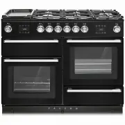
7 A B C D E F 2. Range Overview The 110 dual fuel cooker (Fig. 2.1) has the following features: A. 4 hotplate burners, a Wok Burner and a Ceramic Multizone hotplate B. Control Panel C. Glide-out Grill™ with 4 position Trivet D. Multifunction Oven E. Steam cavity F. Bread Proving/Storage Drawer Hotpl...
Page 11 - Wok Burner
8 ArtNo.311-0007 Wok stand close-up ArtNo.311-0006 Correct wok sizes ArtNo.311-0002 Pan with rim ArtNo.311-0001 Right pans gas Art No. 311-0003 Simmer aids ArtNo.311-0004 Tipping wok If and when you let go of the control knob or the burner goes out, then the FSD has not been bypassed. Turn the contr...
Page 12 - The Ceramic Hotplate
9 ArtNo.274-0008 Prof DL warmer control 1 ArtNo.274-0008 Prof DL warmer control 1 The Ceramic Hotplate The hotplate area on the left-hand side is dual purpose. It can be used either as a ceramic hob to heat a pan in the usual way ( Fig. 2.11 ) or it can be used to heat the supplied griddle. The rear...
Page 13 - The Griddle
10 Fig. 2.21 ArtNo.312-0006 Correct pan sizes ArtNo.274-0008 Prof DL warmer control 1 The Griddle The griddle ( Fig. 2.17 ) is designed to fit securely on the locating pins over the ceramic heating area ( Fig. 2.18 ). DO NOT try to use it over one of the gas burners. It will not be securely held and...
Page 14 - Bread Proving Drawer; TOP TIPS
11 Bread Proving Drawer The Bread Proving Drawer is found on the right at the base of the cooker ( Fig. 2.22 ). Within the Bread Proving Drawer there are slots in the base to allow warmed air to flow through into the drawer from the element underneath.The Bread Proving Drawer temperature is ideal fo...
Page 16 - Four grill height positions; To switch on both elements
13 Nearest to the element Middle High Middle Low Furthest from the element 3. Using the Glide-out Grill™ 180o 180o 180o 180o Nearest to the element Middle Low Middle High Furthest from the element Four grill height positions Four grill height positions refer to Fig. 3.5 To switch on both elements Fi...
Page 17 - The Multifunction Oven; To select a cooking function
14 4. The Multifunction Oven The clock must be set to the time of day before the oven will work. See the section on ‘The Clock’ for instructions on setting the time of day. References to ‘left-hand’ and ‘right-hand’ ovens apply as viewed from the front of the appliance. The left-hand oven is a multi...
Page 18 - Rapid heat mode can only be activated when the Fan; Oven Lights; Display Lock
15 ECO Mode This setting saves energy, cooking in fanned mode, for foods requiring a cooking time of 45 minutes or less. No preheating . Note: The oven door must remain closed during ECO mode. Failure to do so will result in the oven continuing to cook after the pre-set 45 minutes.The following food...
Page 19 - Accessories; Glide-out Oven Shelves; To remove the glide-out shelf; Steam cavity Shelves
16 Front Accessories Glide-out Oven Shelves The left-hand oven is supplied with 2 glide-out oven shelves.To fit the glide-out shelf, hook the front of the shelf onto the runners as shown ( Fig. 4.3 ). The rear of the shelf should rest on the runners, in front of the rear stop ( Fig. 4.3 ). The glide...
Page 20 - The clock must be set to the time of day before the multi-
17 ArtNo.320-0015 Fitting the Handyack 1 ArtNo.320-0014 Handyrack on LH door ArtNo.320-0016 Fitting the handyrack 2 The Handyrack (Optional extra) The Handyrack ( Fig. 4.11 ) fits to the left-hand oven door only. Food cooking on it is easy to attend to, because it is accessible when the door is open...
Page 21 - To stop the multifunction oven after a specific time; To start and then stop the multifunction oven; Note
18 4. Once the specified time has elapsed an alarm will sound. It will stop automatically after 10 seconds. 5. To cancel the minute minder, and enter a new time, tap the clock button whilst the [ ] symbol is active. To stop the multifunction oven after a specific time 1. Set the cooking function and...
Page 22 - Cooking Tips; Tips on cooking with the timer; DO NOT place warm food in the oven to be timed.; General oven tips; When the oven is on, DO NOT leave the door open for
19 Cooking Tips Tips on cooking with the timer If you want to cook more than one dish, choose dishes that require approximately the same cooking time. However, dishes can be ‘slowed down’ slightly by using small containers and covering them with aluminium foil, or ‘speeded up’ slightly by cooking sm...
Page 23 - Cooking Table
20 Oven Shelf Positions Top (T) Centre (C) Base (B) ArtNo.050-0007 Oven shelf positions The oven control settings and cooking times given in the table below are intended to be used as a guide only . Individual tastes may require the temperature to be altered to provide a preferred result. Food is co...
Page 24 - The Steam Cavity; left hand; The base of the steam cavity will remain HOT after
21 Water tank lid 5. The Steam Cavity The Steam Cavity (right-hand) The steam cavity is shown in Fig. 5.1 . Fig. 5.2 shows the touch sensitive control panel for the steam cavity. Water Level To fill the water tank or check the water level lift and pull the water tank from the oven cavity ( Fig. 5.1 ...
Page 25 - Operating the Steam Cavity
22 Fig. 5.4 Fig. 5.5 Fig. 5.6 Fig. 5.7 Fig. 5.8 Fig. 5.9 Fig. 5.10 Fig. 5.11 Fig. 5.12 Operating the Steam Cavity Note: The steam cavity may start a pump out cycle ( Fig. 5.12 ) when first turned on. This is normal and it should be allowed to complete. The cycle will take approximately 2 minutes. 1....
Page 28 - Essential Information; The Single Ring Burners; Cleaning Your Cooker
25 A B C D A – inner burner cap, B – outer burner cap, C – burner head, D – wok burner base Essential Information Isolate the electricity supply before carrying out any thorough cleaning. Allow the cooker to cool. n Never use paint solvents, washing soda, caustic cleaners, biological powders, bleach...
Page 29 - Ceramic Hotplate; Daily Care; IMPORTANT: Use an oven glove to protect your hand from
26 Ceramic Hotplate Daily Care First of all, make sure that the heat indicator light is off and that the cooking surface is cool. Apply a small dab of ceramic cleaning cream in the centre of the area to be cleaned. Dampen a clean paper towel and work the cream onto the cooking surface. As a final st...
Page 30 - Grills; Before you remove any of the grill parts for cleaning,; Cleaning the Glide-out Grill; DO NOT put the side runners in a dishwasher.
27 Grills The grill pan and trivet should be washed in hot soapy water. Alternatively, the grill pan can be washed in a dishwasher.After grilling meats or any foods that soil, leave to soak for a few minutes immediately after use. Stubborn particles may be removed from the trivet using a nylon brush...
Page 31 - DO NOT use harsh abrasive cleaners or sharp metal; Multifunction Oven; ‘Cook & Clean’ Panels
28 Control Panel and Doors Avoid using any abrasive cleaners, including cream cleaners. For best results, use a liquid detergent.The same cleaner can also be used on the doors. Alternatively, use a soft cloth wrung out in clean hot soapy water. You can use the same method for cleaning the control pa...
Page 32 - Steam Cavity
29 Steam Cavity n Before cleaning your oven or performing maintenance, please switch off the power supply. In order to prolong the service life of steam cavity, please note the following points: The enameled or stainless steel parts should be washed with lukewarm water without using any abrasive pow...
Page 33 - Cleaning Table
30 Cleaning Table Cleaners listed (Table 6.1) are available from supermarkets or electrical retailers as stated. For enamelled surfaces use a cleaner that is approved for use on vitreous enamel.Regular cleaning is recommended. For easier cleaning, wipe up any spillages immediately. HotplatePart Fini...
Page 36 - Error Codes
33 Error Codes Multifunction oven Error Code Error description Comment HE 1 Oven sensor NTC short circuit or open circuit HE 2 Meat probe short circuit Not applicable HE 3 Communication problem between UI and power PCB Steam cavity Error Code Error description Comment HE 1 Oven sensor NTC short circ...
Page 37 - If You Have a Problem
INSTALLATION Check the appliance is electrically safe when you have finished. 34 Firstly, please complete the appliance details below and keep them safe for future reference – this information will enable us to accurately identify the particular appliance and help us to help you. Filling this in now...
Page 40 - INSTALLATION; Positioning the Cooker; Overhead – Measurement A
INSTALLATION Check the appliance is gas sound when you have finished. 37 ArtNo.110-0023 - 110 - cooker clearances (AUS) Hob Trivet Horizontal combustible surface B C D E A * or 130 mm min Positioning the Cooker The diagram ( Fig. 9.1 ) shows the minimum recommended distance from the cooker to nearby...
Page 42 - Fitting a Stability Bracket; MUST
INSTALLATION Check the appliance is gas sound when you have finished. 39 ArtNo.070-0014 - Stability bracket - Wall fitting Cooker Stability bracket Floor Stability location bracket Wall Typical wall mounting ArtNo.070-0014 - Stability bracket - Wall fitting Cooker Stability bracket Floor Stability l...
Page 43 - Gas Connection
INSTALLATION Check the appliance is gas sound when you have finished. 40 Gas Connection This must be in accordance with the relevant standards.The gas supply needs to terminate with a down-facing threaded fitting ½” connection. The inlet connector is located just below the hotplate level at the rear...
Page 44 - Electrical Connection; Current Operated Earth Leakage Breakers
INSTALLATION Check the appliance is gas sound when you have finished. 41 Electrical Connection This appliance must be installed by a qualified electrician to comply with with current AS/NZS 3000 Wiring Rules and regulations in force.Make sure that the mains characteristics (voltage, nominal, power, ...
Page 46 - Final Fittings and Checks; Hob Check; Customer Care
INSTALLATION Check the appliance is gas sound when you have finished. 43 Final Fittings and Checks Hob Check Check each cooking zone in turn. Be sure to use pans of the correct size and material. Grill Check Turn on the grill control and check that the grill heats up. Oven Check Set the clock as des...
Page 47 - Hotplate; Injectors; Bypass Screw Adjustment; Conversion to LP Gas
WARNING – SERVICING TO BE CARRIED OUT ONLY BY AN AUTHORISED PERSON Disconnect from electricity and gas before servicing. Check appliance is safe when you have finished. 44 Conversion from Natural Gas (1.0 kPa) to LPG X Propane (2.54 kPa) n A suitably competent person must perform the conversion. Aft...
Page 48 - WARNING – SERVICING TO BE CARRIED OUT ONLY BY AN AUTHORISED PERSON; Set the Governor; Check the appliance is gas sound.; Affix Label
WARNING – SERVICING TO BE CARRIED OUT ONLY BY AN AUTHORISED PERSON Disconnect from electricity and gas before servicing. Check appliance is safe when you have finished. 45 Set the Governor Unscrew the governor’s brass top. In the base of the brass top is a plastic snap-in converter device ( Fig. 10....
Page 50 - Controls
WARNING – SERVICING TO BE CARRIED OUT ONLY BY AN AUTHORISED PERSON Disconnect from electricity before servicing. Check appliance is safe when you have finished. 47 reconnected. Take care not to damage the ignition electrodes of the burners.It is important that the rear earthing leads are replaced wh...
Page 53 - Doors
WARNING – SERVICING TO BE CARRIED OUT ONLY BY AN AUTHORISED PERSON Disconnect from electricity before servicing. Check appliance is safe when you have finished. 50 Top Element Open the left-hand oven door and undo the fixings that secure the heat shield. Remove the top element bracket fixings and wi...
Page 55 - Circuit Diagram
52 E A N a b e f c d 1 2 1.1kW 1.1kW Po wer PCB Po wer PCB Steam Oven X02 X30 X28 X26 X26 X26 X27 X27 X27 X03 X04 X42 X16 X42 X22 X23 X31 X21 X08 X09 X11 X10 X33 X34 X34 b b b b b b b b br br br br v v v v v b r r bk r v v br br br b b v v r r b bk br br br bk r br bk bk br y r b y v y r y b bk bk v...
Page 56 - Power PCB
53 Rotisserie(Not Used) Con 15 Con 2 Con 7 Con 5 Con 10 Con 8 Con 1 Con 4 Con 6C on 3 Connector P2 Connector P1 Protective Earth PE 11 Function UI (X43) Steam Oven UI (X44) M M M M M ACN A5 A4 A9 A3 A8 A2 A7 A1 A6 A11 A12 A10 ACL N A X46 X45 X47 X48 X49 X50 X51 X52 X27 X11 X09 X10 X08 X53 X54 X31 X1...
Page 57 - Pressures; Dimensions; Oven Efficiency
54 13. Technical Data THE COOKER IS CATEGORY: CatII2H3+ . It is supplied set for group H natural gas. A conversion kit from NG to LP is available for the cooker. INSTALLER: Please leave these instructions with the user. DATA BADGE LOCATION: Cooker back, serial number repeater badge below oven door o...