Page 3 - Contents; Cleaning Your Cooker
i Contents 1. Before You Start... 1 Personal Safety 1 Electrical Connection Safety 2 If You Smell Gas 2 Peculiar Smells 2 Cooling Fan 2 Ventilation 3Maintenance 3Hob Care 5 Grill/Glide-out Grill™ Care 6 Cooker Care 6 Cleaning 6 2. Cooker Overview 7 Hotplate Burners 7 Wok Burner 8 The Wok Cradle 8 Th...
Page 4 - ii
Page 5 - Personal Safety
1 Your cooker should give you many years of trouble-free cooking if installed and operated correctly. It is important that you read this section before you start. Personal Safety This appliance is for cooking purposes only. It must not be used for other purposes, for example heating a room. Using it...
Page 6 - Electrical Connection Safety; THE APPLIANCE MUST BE; Gas Connection Safety; DO NOT; Peculiar Smells
2 • Always keep combustible materials, e.g. curtains, and flammable liquids a safe distance away from the cooker. • DO NOT spray aerosols in the vicinity of the cooker while it is on. Electrical Connection Safety n WARNING: THE APPLIANCE MUST BE EARTHED. The cooker is preset for a single-phase earth...
Page 8 - Oven Care
4 FRONT Rear stop Front bracket ArtNo.324-0001 Steam burst • DO NOT modify this appliance. This appliance is not intended to be operated by means of external timer or separated remote-control system. • If flammable materials are stored in the drawer, oven(s) or grill(s) it may explode and result in ...
Page 11 - Hotplate Burners
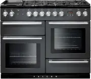
7 A B C D E F 2. Cooker Overview The 110 dual fuel cooker (Fig. 2.1) has the following features: A. 4 hotplate burners, a Wok Burner and a Ceramic Multizone hotplate B. Control Panel C. Glide-out Grill™ with 4 position Trivet D. Multifunction Oven E. Fan Oven F. Bread Proving/Storage Drawer Hotplate...
Page 12 - Wok Burner
8 ArtNo.311-0007 Wok stand close-up ArtNo.311-0006 Correct wok sizes ArtNo.311-0002 Pan with rim ArtNo.311-0001 Right pans gas Art No. 311-0003 Simmer aids ArtNo.311-0004 Tipping wok If and when you let go of the control knob or the burner goes out, then the FSD has not been bypassed. Turn the contr...
Page 13 - The Ceramic Hotplate
9 ArtNo.274-0008 Prof DL warmer control 1 ArtNo.274-0008 Prof DL warmer control 1 The Ceramic Hotplate The hotplate area on the left-hand side is dual purpose. It can be used either as a ceramic hob to heat a pan in the usual way ( Fig. 2.11 ) or it can be used to heat the supplied griddle plate.The...
Page 14 - The Griddle Plate
10 ArtNo.274-0008 Prof DL warmer control 1 Fig. 2.21 ArtNo.312-0006 Correct pan sizes The Griddle Plate The griddle plate ( Fig. 2.17 ) is designed to fit securely on the locating pins over the ceramic heating area ( Fig. 2.18 ). DO NOT try to use it over one of the gas burners. It will not be secur...
Page 15 - Bread Proving Drawer
11 F Bread Proving Drawer The Bread Proving Drawer is found on the right at the base of the cooker ( Fig. 2.22 ). Within the Bread Proving Drawer there are slots in the base to allow warmed air to flow through into the drawer from the element underneath.The Bread Proving Drawer temperature is ideal ...
Page 16 - The Multifunction Oven
12 Cleaning Clean the inside of the drawer with hot soapy water and a soft cloth, rinse and dry.The Bread Proving Drawer is ideal for storing baking trays and other cooking utensils.It can get warm, so do not store anything in it that may melt or catch fire. n Never store flammable materials in the ...
Page 17 - Multifunction Oven Functions
13 Multifunction Oven Functions Defrost This function operates the fan to circulate cold air only. Make sure the temperature control is at 0°C and that no heat is applied. This enables small items such as desserts, cream cakes and pieces of meat, fish and poultry to be defrosted.Defrosting in this w...
Page 18 - Fan Oven; Oven Lights
14 ArtNo.320-0017 Main oven light ArtNo.270-0005 Proplus electric oven control Function control Temperature control ArtNo.270-0006 Proplus oven control light Fig. 2.24 Fig. 2.25 Fig. 2.26 Fig. 2.27 Fan Oven The right-hand oven is a fan oven that circulates hot air continuously, which means faster, m...
Page 19 - Accessories; The Handyrack
15 ArtNo.320-0014 Handyrack on LH door FRONT Rear stop Front bracket 1 2 2 1 Accessories Glide-out Shelves The oven shelves ( Fig. 2.28 ) are retained when pulled forward but can be easily removed and refitted.Both ovens are supplied with glide-out oven shelves. To fit the glide-out shelves, hook th...
Page 21 - Minute Minder; To stop the oven at a specific time of day
17 ArtNo.306-0001 - 3-button clock ArtNo.306-0001 - 3-button clock ArtNo.306-0001 - 3-button clock ArtNo.306-0001 - 3-button clock ArtNo.306-0001 - 3-button clock ArtNo.306-0001 - 3-button clock Step. 1 Step. 1 Step. 2 Step. 3 Step. 1 Step. 2 ArtNo.306-0001 - 3-button clock ArtNo.306-0001 - 3-button...
Page 23 - Tips on cooking with the timer; General oven tips
19 5. Cooking Tips Tips on cooking with the timer If you want to cook more than one dish, choose dishes that require approximately the same cooking time. However, dishes can be ‘slowed down’ slightly by using small containers and covering them with aluminium foil, or ‘speeded up’ slightly by cooking...
Page 25 - Essential Information; The Single Ring Burners
21 A B C D A – inner burner cap, B – outer burner cap, C – burner head, D – wok burner base Essential Information Isolate the electricity supply before carrying out any thorough cleaning. Allow the cooker to cool. n Never use paint solvents, washing soda, caustic cleaners, biological powders, bleach...
Page 26 - Ceramic Hotplate
22 Ceramic Hotplate Daily Care First of all, make sure that the heat indicator light is off and that the cooking surface is cool. Apply a small dab of ceramic cleaning cream in the centre of the area to be cleaned. Dampen a clean paper towel and work the cream onto the cooking surface. As a final st...
Page 27 - Grills; Cleaning the Glide-out Grill
23 Grills The grill pan and trivet should be washed in hot soapy water. Alternatively, the grill pan can be washed in a dishwasher.After grilling meats or any foods that soil, leave to soak for a few minutes immediately after use. Stubborn particles may be removed from the trivet using a nylon brush...
Page 28 - Ovens
24 Control Panel and Doors Avoid using any abrasive cleaners, including cream cleaners. For best results, use a liquid detergent.The same cleaner can also be used on the doors. Alternatively, use a soft cloth wrung out in clean hot soapy water. You can use the same method for cleaning the control pa...
Page 29 - Cleaning Table
25 Cleaning Table Cleaners listed (Table 7.1) are available from supermarkets or electrical retailers as stated. For enamelled surfaces use a cleaner that is approved for use on vitreous enamel.Regular cleaning is recommended. For easier cleaning, wipe up any spillages immediately. HotplatePart Fini...
Page 31 - Grill
27 Oven light is not working The bulb has probably burnt out. You can buy a replacement bulb (which is not covered under the warranty) from a good electrical shop. Ask for a 40 W - 230 V halogen lamp (G9) ( Fig. 8.1 ). Turn off the power at the circuit breaker.Before removing the existing bulb, turn...
Page 32 - If You Have a Problem; Service and Spares
INSTALLATION Check the appliance is electrically safe when you have finished. 28 Firstly, please complete the appliance details below and keep them safe for future reference – this information will enable us to accurately identify the particular appliance and help us to help you. Filling this in now...
Page 34 - Positioning the Cooker
INSTALLATION Check the appliance is gas sound when you have finished. 30 You will need the following equipment to complete the cooker installation satisfactorily: • * Restraining chain and hook: If the cooker is to be supplied with gas through a flexible hose, a restraining chain and hook MUST be fi...
Page 37 - Fitting a Stability Bracket
INSTALLATION Check the appliance is gas sound when you have finished. 33 ArtNo.070-0014 - Stability bracket - Wall fitting Cooker Stability bracket Floor Stability location bracket Wall Typical wall mounting ArtNo.070-0014 - Stability bracket - Wall fitting Cooker Stability bracket Floor Stability l...
Page 38 - Gas Connection
INSTALLATION Check the appliance is gas sound when you have finished. 34 Gas Connection This must be in accordance with the relevant standards.The gas supply needs to terminate with a down-facing threaded fitting ½” connection. The inlet connector is located just below the hotplate level at the rear...
Page 39 - Electrical Connection
INSTALLATION Check the appliance is gas sound when you have finished. 35 Electrical Connection This appliance must be installed by a qualified electrician to comply with with current AS/NZS 3000 Wiring Rules and regulations in force.Make sure that the mains characteristics (voltage, nominal, power, ...
Page 40 - Fixed Wiring
INSTALLATION Check the appliance is gas sound when you have finished. 36 Fixed Wiring n Disconnect from the mains supply. For connection to fixed wiring, i.e. flexible conduit, Remove the electrical terminal cover on the back panel ( Fig. 10.14 ). Remove the M4 screw securing the reducer plates to t...
Page 41 - Final Fittings and Checks; Customer Care
INSTALLATION Check the appliance is gas sound when you have finished. 37 Final Fittings and Checks Hob Check Check each cooking zone in turn. Be sure to use pans of the correct size and material. Grill Check Turn on the grill control and check that the grill heats up. Oven Check Set the clock as des...
Page 42 - Hotplate; Bypass Screw Adjustment; Conversion to LP Gas
WARNING – SERVICING TO BE CARRIED OUT ONLY BY AN AUTHORISED PERSON Disconnect from electricity and gas before servicing. Check appliance is safe when you have finished. 38 Conversion from Natural Gas (1.0 kPa) to LPG X Propane (2.54 kPa) n A suitably competent person must perform the conversion. Aft...
Page 43 - Set the Governor; Affix Label
WARNING – SERVICING TO BE CARRIED OUT ONLY BY AN AUTHORISED PERSON Disconnect from electricity and gas before servicing. Check appliance is safe when you have finished. 39 Set the Governor Unscrew the governor’s brass top. In the base of the brass top is a plastic snap-in converter device ( Fig. 11....
Page 45 - Controls
WARNING – SERVICING TO BE CARRIED OUT ONLY BY AN AUTHORISED PERSON Disconnect from electricity before servicing. Check appliance is safe when you have finished. 41 reconnected. Take care not to damage the ignition electrodes of the burners.It is important that the rear earthing leads are replaced wh...
Page 46 - Grill
WARNING – SERVICING TO BE CARRIED OUT ONLY BY AN AUTHORISED PERSON Disconnect from electricity before servicing. Check appliance is safe when you have finished. 42 3.3 To Change the Ignition Generator n DISCONNECT FROM THE ELECTRICITY SUPPLY. Pull the cooker forwards to gain access to the cover box ...
Page 47 - Ovens
WARNING – SERVICING TO BE CARRIED OUT ONLY BY AN AUTHORISED PERSON Disconnect from electricity before servicing. Check appliance is safe when you have finished. 43 5 Ovens 5.1 To Replace an Oven Thermostat n DISCONNECT FROM THE ELECTRICITY SUPPLY. Remove the control panel and hotplate ( see 1.1 &...
Page 48 - Doors
WARNING – SERVICING TO BE CARRIED OUT ONLY BY AN AUTHORISED PERSON Disconnect from electricity before servicing. Check appliance is safe when you have finished. 44 5.5 To Remove the Right-hand Oven Element n DISCONNECT FROM THE ELECTRICITY SUPPLY. Remove the oven inner back ( see 5.2 ). Remove the 2...
Page 50 - Circuit Diagram
46 1 2 a b e f c d 1 2 1.1kW 1.1kW P095199 1 2 P2 P1 P095199 1 2 P2 P1 P095199 1 2 P2 P1 P095199 1 2 P2 P1 P095199 1 2 P2 P1 P095199 1 2 P2 P1 E A N B2 P028728 6 P6 5 P5 4 P4 7 P7 8 P8 2 P2 1 P1 3 P3 bk D2 A1 B3B4 B5B6 B7 C D1 D3 D4 H1 H2 I I I H2 G1 G3 J J J J K M1 J B2 M2 A3 F1 B1 G2 A4 A2 M3 w r ...
Page 51 - Pressures; Dimensions; Oven Efficiencies
47 14. Technical Data This cooker is designed for use on Natural gas, although a conversion for LP (LPG X Propane (2.54 kPa)) gas is included. INSTALLER: Please leave these instructions with the user. DATA BADGE LOCATION: Cooker back, serial number repeater badge below oven door opening. COUNTRY OF ...