Page 3 - Contents; Cleaning your cooker
i Contents 1. Before You Start... 1 Electrical Connection Safety 2 Peculiar Smells 3 Ventilation 3Maintenance 3Induction care 4 Grill/Glide-out Grill™ Care 7 Cooling Fan 7 Cooker Care 7 Cleaning 8 2. Cooker Overview 9 The Hob 9 The Glide-out Grill 13 The Ovens 14 Operating the Ovens 14 Main Oven Lig...
Page 4 - ii
Page 5 - Personal Safety; DO NOT operate this appliance before
1 Your cooker should give you many years of trouble-free cooking if installed and operated correctly. It is important that you read this section before you start.This User Guide covers a number of different models. Although some of the illustrations will look different to your particular model, the ...
Page 6 - Electrical Connection Safety; THE APPLIANCE MUST BE
2 ArtNo.132-0001 - 1 phase 240Vac 50Hz 1-phase 230 V AC 50 Hz Electrical Connection Safety n n WARNING: THE APPLIANCE MUST BE EARTHED. The cooker is preset for a single-phase earthed electrical connection. It is essential to install a multi-pole circuit breaker that completely disconnects the applia...
Page 8 - Induction care; IMPORTANT INFORMATION FOR
4 Induction care • IMPORTANT INFORMATION FOR PACEMAKER AND IMPLANTED INSULIN PUMP USERS: The functions of this hob comply with the applicable European standards on electromagnetic interference. If you are fitted with a pacemaker or implanted insulin pump and are concerned please consult your doctor ...
Page 10 - DO NOT leave the hob unattended.; Oven Care; DO NOT use harsh abrasive cleaners or
6 • We recommend that you avoid wiping any surface unit areas until they have cooled and the indicator light has gone off. Sugar spills are the exception to this (see ‘Cleaning your Cooker’). After cleaning, use a dry cloth or paper towel to remove any cleaning cream residue. • The ceramic surface s...
Page 12 - Cleaning
8 Cleaning • Isolate the electricity supply before carrying out any thorough cleaning. Allow the cooker to cool. • In the interests of hygiene and safety, the cooker should be kept clean at all times as a build up in fats and other food stuff could result in a fire. • Clean only the parts listed in ...
Page 13 - The Hob; The kind of pan you use and the
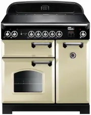
9 The 90 induction cooker (Fig. 2.1) has the following features: A. 5 induction cooking zones B. A control panel C. A separate Glide-out Grill™ D. Main, programmable fan oven E. Tall fan oven The Hob Use only pans that are suitable for induction hobs. We recommend stainless steel, enamelled steel pa...
Page 14 - Residual Heat Indicator,
10 Max: 1.85 kW Boost: 2.5 kW Max: 1.85 kW Boost: 3.0 kW Max: 1.85 kW Boost: 2.5 kW Max: 1.15 kW Boost: 2.0 kW Max: 1.15 kW Boost: 2.0 kW Zone 1 Zone 2 Zone 3 Zone 5 Zone 4 Make sure that the base of the pan is clean and dry to prevent any residue burning onto the hob panel. This also helps prevent ...
Page 16 - Low Temperature Setting,; This function should only be used when heating; Power Boost Setting,; Power Level
12 Low Temperature Setting, L1 / L2 n n This function should only be used when heating from cold Each cooking area is equipped with 2 low temperature settings: • L1 will maintain a temperature of about 40 °C – ideal for gently melting butter or chocolate. • L2 will maintain a temperature of about 90...
Page 18 - The Ovens; The clock must be set to the time of day before the ovens; ‘The Clock’; for; References to ‘left-hand’ and ‘right-hand’ ovens apply as viewed; Operating the Ovens; ‘Troubleshooting’
14 ArtNo.235-0005 - Classic DL oven control 2 ArtNo.320-0026 - Oven light The Ovens The clock must be set to the time of day before the ovens will work. See the following section on ‘The Clock’ for instructions on setting the time of day. References to ‘left-hand’ and ‘right-hand’ ovens apply as vie...
Page 19 - Accessories
15 Accessories Oven Shelves – Left-hand (Main) Oven The oven shelves (Fig. 2.17) are retained when pulled forward but can be easily removed and refitted. Pull the shelf forward until the back of the shelf is stopped by the shelf stop bumps in the oven sides (Fig. 2.18).Lift up the front of the shelf...
Page 20 - The clock must be set to the time of day before the oven; Setting the Clock; NOTE
16 ArtNo.300-0005 2BC minute minder setting E A B ArtNo.300-0005 2BC minute minder setting A B C D The clock must be set to the time of day before the oven will work. Setting the Clock 1. Once the cooker is connected and switched on, the display will start to flash. 2. To set the time, turn the Time...
Page 21 - To stop the oven at a specific time of day; TOP TIP
17 D A B A B ArtNo.311-0004 RShaw 2BC stoppingOven 1 H A B To stop the oven at a specific time of day You have set the required temperature and function mode and you would like the oven to automatically stop. TOP TIP Make a note of the current time so you do not forget. 1. Turn the Timer (A) knob to...
Page 22 - To start and stop the oven automatically; “Cancel the timer alarm” on page 16; Reset to manual cooking; Adjusting (B) knob counter clockwise until the tone bars are
18 C A B C A B To start and stop the oven automatically The timer allows you to automatically start and stop by a combination of the length of the cooking time and the stop time. Giving you the flexibility to cook casseroles etc while you are out. You cannot set the actual start time. 1. Turn the Ti...
Page 23 - Using the clock; Setting the clock
19 4. 3 Button clock Using the clock You can use the clock to turn the programmable oven on and off. The clock must be set to the time of day before the oven will work.NOTE: When using the timer functions, first set the clock as required before setting the oven temperature. The oven can be switched ...
Page 27 - Hob; Daily care
23 ArtNo.312-0010 Cleaning; scraping the ceramic hob n n Isolate the electricity supply before carrying out any major cleaning. Then allow the cooker to cool. n n NEVER use paint solvents, washing soda, caustic cleaners, biological powders, bleach, chlorine based bleach cleaners, coarse abrasives or...
Page 28 - Grills; Before you remove any of the grill parts for cleaning,; Removing the glide-out grill pan; DO NOT put the side runners in a dishwasher.; Control panel and doors
24 Grills The grill pan and trivet should be washed in hot soapy water. After grilling meats or any foods that soil, leave to soak for a few minutes immediately after use. Stubborn particles may be removed from the trivet using a nylon brush. Alternatively, the grill pan can be washed in a dishwashe...
Page 29 - Glass fronted door panels; DO NOT use harsh abrasive cleaners or sharp metal; Ovens; ‘Cook & Clean’ Panels; Removing the panels to clean the enamel interior; Tall oven
25 ArtNo.320-0002b - Oven door side screws (Toledo) Glass fronted door panels The oven door front panels can be taken off so that the glass panels can be cleaned. Move the cooker forward to gain access to the sides (see the ‘Moving the Cooker’ section under ‘Installation’).Open the oven door slightl...
Page 30 - Cleaning table; Cleaners listed (Table 7.1) are available from supermarkets or; up any spillages immediately.
26 Cleaning table Cleaners listed (Table 7.1) are available from supermarkets or electrical retailers as stated. For enamelled surfaces use a cleaner that is approved for use on vitreous enamel.Regular cleaning is recommended. For easier cleaning, wipe up any spillages immediately. HotplatePart Fini...
Page 34 - If You Have a Problem; Service and Spares
INSTALLATION Check the appliance is electrically safe when you have finished. 30 Firstly, please complete the appliance details below and keep them safe for future reference – this information will enable us to accurately identify the particular appliance and help us to help you. Filling this in now...
Page 35 - INSTALLATION; Safety Requirements and Regulations; The cooker must be installed in a well-ventilated; ‘Electrical Connection’; Read these instructions before installing or using; Provision of Ventilation; You will need the following equipment to complete the
31 INSTALLATION Check the appliance is electrically safe and gas sound when you have finished. Safety Requirements and Regulations n n The cooker must be installed in a well-ventilated space, in accordance with the section entitled ‘Electrical Connection’ . n n Read these instructions before install...
Page 36 - Positioning the Cooker; *Any cookerhood should be installed in accordance with the; Moving the Cooker
32 INSTALLATION Check the appliance is electrically safe and gas sound when you have finished. ArtNo.090-0024 - 90 induction door clearances 130 mm min ArtNo.090-0028 - 90 cooker min spacing GENERIC 75 mm min 75 mm min 650 mm min 905 mm min 930 mm max ArtNo.090-0017 - 90 6BC min positions above cook...
Page 37 - Lowering the Two Rear Rollers; DO NOT use the door handles or control knobs to; Fitting the Stability Bracket
33 INSTALLATION Check the appliance is electrically safe and gas sound when you have finished. ArtNo.070-0014 - Stability bracket - Wall fitting Cooker Stability bracket Floor Stability location bracket Wall Typical wall mounting ArtNo.070-0014 - Stability bracket - Wall fitting Cooker Stability bra...
Page 38 - Electrical Connection
34 INSTALLATION Check the appliance is electrically safe and gas sound when you have finished. ArtNo.132-0001 - 1 phase 240Vac 50Hz 1-phase 230 V AC 50 Hz Electrical Connection This appliance must be installed by a qualified electrician to comply with with current AS/NZS 3000 Wiring Rules and regula...
Page 39 - Fixed Wiring; Disconnect from the mains supply.; fittings located at the top of the box. Remove the M4 screw
35 INSTALLATION Check the appliance is electrically safe and gas sound when you have finished. Fixed Wiring n n Disconnect from the mains supply. For connection to fixed wiring, i.e. flexible conduit, remove the electrical terminal cover on the back panel (Fig. 9.13). Fit the conduit box to the cook...
Page 40 - Final Checks; The handles should be above the fixings.; Customer Care; Installer: Please complete your details in this guide, inform
36 INSTALLATION Check the appliance is electrically safe and gas sound when you have finished. ArtNo.350-0010 - Fitting the plinth 1 (Kitchener) Art No 215-0028 - Handrail fascia fixings ArtNo.210-0009 - Classic removing the handles ArtNo.215-0026 - Handle gaskets fixed Final Checks After completing...
Page 44 - Verify the door operation.
WARNING – SERVICING TO BE CARRIED OUT ONLY BY AN AUTHORISED PERSON Disconnect from electricity before servicing. Check appliance is safe when you have finished. 40 ArtNo.320-0002a Proplus oven door side screws ArtNo.320-0007 Oven door hinge adjustment 2 ArtNo.320-0006 Oven door hinge adjustment 1 Ef...
Page 45 - To Replace the Tall oven Magnetic Latch
WARNING – SERVICING TO BE CARRIED OUT ONLY BY AN AUTHORISED PERSON Disconnect from electricity before servicing. Check appliance is safe when you have finished. 41 ArtNo.320-0005 Oven door rubber seal Fig. 10.11 6.6 To Adjust the Main Oven Door Catch Keep Open the oven door, and slacken off the lock...
Page 46 - Circuit Diagrams; INDUCTION UNIT
42 11. Circuit Diagrams Hob 1 2 5 3 4 E54321 INTERFACE BOARD 12 5 3 4 INDUCTION UNIT HOB DISPLAY EarthN(6)N(5) L(2) L(3) On Terminal Block On Terminal Block On Terminal Block w/br g/y b b br br w/br w/br w/br w/br KeyThe connections shown in the circuit diagram are for single-phase. The ratings are ...
Page 47 - Oven; Code Colour
43 Oven P095199 1 2 1 P1 P1 P2 E P095199 1 2 1 P1 P1 P2 P095199 1 2 1 P1 P1 P2 A b b b br br br r v r r br br v r y b br b r or y y y y y v y or g/y b br br b bk r v br or v bk bk g/y y y b y b b or br v r bk rr bk b b b y v v br r bk r b br r bb br br br br b b b b b br br b b y b b bk b y bk r br ...
Page 48 - 08 mm excluding handles, 670 mm including handles; Hotplate Ratings; Large; Time to cook standard load
44 12. Technical Data INSTALLER: Please leave these instructions with the user.DATA BADGE LOCATION: Cooker back, serial number repeater badge below the oven door opening.COUNTRY OF DESTINATION: Australia. Connections Electric 230 / 400 V ~ 50 Hz 3N Dimensions Total height Min 905 mm Max 930 mm Total...