Page 3 - Contents; Cleaning your cooker
i Contents 1. Before You Start... 1 Personal Safety 1 Electrical Connection Safety 2 Peculiar Smells 3 Ventilation 3Maintenance 3Induction care 4 Grill/Glide-out Grill™ Care 7 Cooling Fan 7 Cooker Care 7 Cleaning 8 2. Cooker Overview 9 The Hob 9 The Glide-out Grill 13 The Ovens 14 Main Oven Light 14...
Page 4 - ii
Page 5 - Personal Safety
1 Your cooker should give you many years of trouble-free cooking if installed and operated correctly. It is important that you read this section before you start. Personal Safety This appliance is for cooking purposes only. It must not be used for other purposes, for example heating a room. Using it...
Page 6 - Electrical Connection Safety; THE APPLIANCE MUST BE
2 ArtNo.132-0001 - 1 phase 240Vac 50Hz 1-phase 230 V AC 50 Hz Electrical Connection Safety n WARNING: THE APPLIANCE MUST BE EARTHED. The cooker is preset for a single-phase earthed electrical connection. It is essential to install a multi-pole circuit breaker that completely disconnects the applianc...
Page 8 - Induction care; IMPORTANT INFORMATION FOR
4 Induction care • IMPORTANT INFORMATION FOR PACEMAKER AND IMPLANTED INSULIN PUMP USERS: The functions of this hob comply with the applicable European standards on electromagnetic interference. If you are fitted with a pacemaker or implanted insulin pump and are concerned please consult your doctor ...
Page 10 - Oven Care; OFF
6 • We recommend that you avoid wiping any surface unit areas until they have cooled and the indicator light has gone off. Sugar spills are the exception to this (see ‘Cleaning your Cooker’). After cleaning, use a dry cloth or paper towel to remove any cleaning cream residue. • The ceramic surface s...
Page 12 - Cleaning
8 Cleaning • Isolate the electricity supply before carrying out any thorough cleaning. Allow the cooker to cool. • In the interests of hygiene and safety, the cooker should be kept clean at all times as a build up in fats and other food stuff could result in a fire. • Clean only the parts listed in ...
Page 13 - The Hob; The kind of pan you use and the
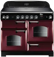
9 Your 110 induction cooker (Fig. 2.1) has the following features: A. 5 induction cooking zones B. Control panel C. A separate Glide-out Grill™ D. A programmable fan oven E. Fan oven F. Storage Drawer The Hob Use only pans that are suitable for induction hobs. We recommend stainless steel, enamelled...
Page 15 - Residual Heat Indicator,; The child lock can only be activated when all
11 Table 2.2 Power Level Auomatic Heat-up Time at 100% (min:sec) 1 0:48 2 2:24 3 3:50 4 5:12 5 6:48 6 2:00 7 2:48 8 3:36 9 Residual Heat Indicator, H After use, a cooking zone will remain hot for a while as heat dissipates. When a cooking zone is switched off the residual heat indicator symbol [ H ]...
Page 16 - Low Temperature Setting,; This function should only be used when heating; Power Boost Setting,; Power Level
12 Low Temperature Setting, L1 / L2 n This function should only be used when heating from cold Each cooking area is equipped with 2 low temperature settings: • L1 will maintain a temperature of about 40 °C – ideal for gently melting butter or chocolate. • L2 will maintain a temperature of about 90 °...
Page 18 - The Ovens; The clock must be set to the time of day before the; ‘The Clock’; for instructions on setting the time of day.; References to ‘left-hand’ and ‘right-hand’ ovens apply as viewed; The Fan Oven; Fan Ovens; Main Oven Light; ‘Troubleshooting’
14 The Ovens The clock must be set to the time of day before the programmable oven will work. See the following section on ‘The Clock’ for instructions on setting the time of day. References to ‘left-hand’ and ‘right-hand’ ovens apply as viewed from the front of the appliance. The left-hand oven is ...
Page 19 - Accessories; Oven Shelves; Storage
15 Accessories Oven Shelves The oven shelves (Fig. 2.15) are retained when pulled forward but can be easily removed and refitted. Pull the shelf forward until the back of the shelf is stopped by the shelf supports (Fig. 2.16) . Lift up the front of the shelf so the back of the shelf will pass under ...
Page 20 - Glide-out Oven Shelf; To fit the glide-out shelf runners
16 1 2 FRONT FRONT Rear stop Front bracket Glide-out Oven Shelf (optional) A glide-out oven shelf is available for either oven ( Fig. 2.22 ). Note: The Handyrack must be removed before fitting the glide-out shelf.The rungs on the shelf supports are in pairs. The glide-out shelf runners can be fitted...
Page 21 - Setting the Clock
17 ArtNo.300-0005 2BC minute minder setting E A B ArtNo.300-0005 2BC minute minder setting A B C D The clock must be set to the time of day before the oven will work. Setting the Clock 1. Once the cooker is connected and switched on, the display will start to flash. 2. To set the time, turn the Time...
Page 22 - To stop the oven at a specific time of day
18 D A B A B ArtNo.311-0004 RShaw 2BC stoppingOven 1 H A B To stop the oven at a specific time of day You have set the required temperature and function mode and you would like the oven to automatically stop. TOP TIP Make a note of the current time so you do not forget. 1. Turn the Timer ( A ) knob ...
Page 24 - Using the clock
20 4. 3 Button clock Using the clock You can use the clock to turn the programmable oven on and off. The clock must be set to the time of day before the oven will work . NOTE : When using the timer functions, first set the clock as required before setting the oven temperature. The oven can be switch...
Page 26 - DO NOT place warm food in the oven to be timed.; General Oven Tips; When the oven is on, DO NOT leave the door open for
22 Hints on Using Your Induction Cooker If you have not used an induction cooker before please be aware of the following: • Make sure that the pans you have or buy are suitable for use on the induction hob. Stainless steel, enamelled steel or cast iron is ideal. Double check before you buy pans – th...
Page 27 - as a
23 6. Cooking Table Oven Shelf Positions Top (T) Centre (C) Base (B) ArtNo.050-0007 Oven shelf positions The oven control settings and cooking times given in the table below are intended to be used as a guide only . Individual tastes may require the temperature to be altered to provide a preferred r...
Page 28 - Hob; Daily care
24 ArtNo.312-0010 Cleaning; scraping the ceramic hob n Isolate the electricity supply before carrying out any major cleaning. Then allow the cooker to cool. n NEVER use paint solvents, washing soda, caustic cleaners, biological powders, bleach, chlorine based bleach cleaners, coarse abrasives or sal...
Page 29 - Grills; Before you remove any of the grill parts for cleaning,; Removing the glide-out grill pan; DO NOT put the side runners in a dishwasher.; Control panel and doors
25 Grills The grill pan and trivet should be washed in hot soapy water. After grilling meats or any foods that soil, leave to soak for a few minutes immediately after use. Stubborn particles may be removed from the trivet using a nylon brush. Alternatively, the grill pan can be washed in a dishwashe...
Page 30 - Glass fronted door panels; DO NOT use harsh abrasive cleaners or sharp metal; Ovens; ‘Cook & Clean’ Panels
26 ArtNo.320-0002b - Oven door side screws (Toledo) Glass fronted door panels The oven door front panels can be taken off so that the glass panels can be cleaned. Move the cooker forward to gain access to the sides (see the ‘Moving the Cooker’ section under ‘Installation’).Open the oven door slightl...
Page 31 - Cleaning table; ) are available from supermarkets or
27 Cleaning table Cleaners listed ( Table 7.1 ) are available from supermarkets or electrical retailers as stated. For enamelled surfaces use a cleaner that is approved for use on vitreous enamel.Regular cleaning is recommended. For easier cleaning, wipe up any spillages immediately. Table 7.1 Hotpl...
Page 35 - If You Have a Problem; Service and Spares
INSTALLATION Check the appliance is electrically safe when you have finished. 31 Firstly, please complete the appliance details below and keep them safe for future reference – this information will enable us to accurately identify the particular appliance and help us to help you. Filling this in now...
Page 36 - Safety Requirements and Regulations; ‘Electrical Connection’; Provision of Ventilation
32 INSTALLATION Check the appliance is electrically safe when you have finished. Safety Requirements and Regulations n The cooker must be installed in a well-ventilated space, in accordance with the section entitled ‘Electrical Connection’ . n Read these instructions before installing or using the a...
Page 37 - Positioning the Cooker; ABOVE; *Any cookerhood should be installed in accordance with the; Moving the Cooker
33 INSTALLATION Check the appliance is electrically safe when you have finished. Positioning the Cooker Fig. 9.1 and Fig. 9.2 shows the minimum recommended distance from the cooker to nearby surfaces.Where the appliance is installed next to cabinetry, the cabinet material must be capable of withstan...
Page 38 - Lowering the Two Rear Rollers; DO NOT ust the door handles or control knobs to; Fitting the Stability Bracket
34 INSTALLATION Check the appliance is electrically safe when you have finished. ArtNo.010-0004 Moving the cooker Lowering the Two Rear Rollers To adjust the height of the rear of the cooker, first fit a 13 mm spanner or socket wrench onto the hexagonal adjusting nut (Fig. 9.5) . Rotate the nut – cl...
Page 39 - Electrical Connection
35 INSTALLATION Check the appliance is electrically safe when you have finished. Electrical Connection This appliance must be installed by a qualified electrician to comply with current AS/NZS 3000 Wiring Rules and regulations in force. Make sure that the mains characteristics (voltage, nominal, pow...
Page 40 - Connection in New Zealand; OR; Fixed Wiring; Disconnect from the mains supply.
36 INSTALLATION Check the appliance is electrically safe when you have finished. Connection in New Zealand Type of cord in accordance with IEC 60227 with a minimum rating of 90°C.Cord size recommended for this application is 3 x 10 mm², three-core cable (Power cables may be sized to take into accoun...
Page 41 - Final Checks; The handles should be above the fixings.; Customer Care
37 INSTALLATION Check the appliance is electrically safe when you have finished. ArtNo.350-0011 - Fitting the plinth 2 (Kitchener) Outer plinth Outer plinth fixing screw Inner plinth ArtNo.350-0010 - Fitting the plinth 1 (Kitchener) ArtNo.350-0012 - Securing the plinth ArtNo.210-0009 - Classic remov...
Page 47 - INDUCTION UNIT; On Terminal Block; Key
43 11. Circuit Diagram Hob 1 2 5 3 4 E54321 INTERFACE BOARD 1 2 54 3 INDUCTION UNIT HOB DISPLAY EarthN(6)N(4) L(2) L(3) On Terminal Block On Terminal Block On Terminal Block w/br w/br w/br w/br w/br Key The connections shown in the circuit diagram are for single-phase. The ratings are for 230 V 50 H...
Page 48 - Oven
44 P095199 2 P2P1 1 P095199 2 P2 P1 1 P095199 2 P2 P1 1 2 1 4 6 br b b b b r b b r b b br v bk bk v v br y b y y y br b br b br b bk b g/y v y y or or g/y r r bk br br y or b bk bk br b r b b v b b r r r v y y y b r b r b b b br br br b br br b br v y v br y br or br E A2 C A1 A N H G1 B3 B4 B2 B1 D...
Page 49 - Please leave these instructions with the user.; Connections; 08 mm excluding handles, 670 mm including handles; Hotplate Ratings; Large
45 12. Technical Data INSTALLER: Please leave these instructions with the user. DATA BADGE LOCATION: Cooker back, serial number repeater badge below the oven door opening. COUNTRY OF DESTINATION: Australia. Connections Electric 230 / 400 V ~ 50 Hz 3N Dimensions Overall height minimum 905 mm maximum ...
Page 50 - NOTES