Page 2 - Contents
i 1. Before You Start... 1 Installation and Maintenance 1 Peculiar Smells 1 If You Smell Gas 1 Ventilation 1 Personal Safety 1 Cooker Care 2 Cleaning 2 2. Cooker Overview 3 Hotplate Burners 3 Wok Burner 4 The Wok Cradle 5 The Griddle 5 The Glide-out Grill 6 The Ovens 7 The Clock 9 Accessories 11 Mai...
Page 3 - Ventilation; If You Smell Gas
1 Thank you for buying a Falcon cooker. It should give you many years of trouble-free cooking if installed and operated correctly. It is important that you read this section before you start, particularly if you have not used a dual fuel cooker before. n n This appliance is designed for domestic coo...
Page 5 - Hotplate Burners; When the control knob is pressed in, sparks will be
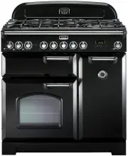
3 C LASSI C DELUXE 90 A B C D E 2. Cooker Overview The 90 dual fuel cooker (Fig.2-1) has the following features: A. 5 hotplate burners including a wok burner B. A control panel C. A glide-out grill D. A main programmable multi-function oven. E. Tall fan oven Hotplate Burners The drawing by each of t...
Page 6 - Wok Burner
4 The igniter should spark and light the gas. Keep holding the knob pressed in to let the gas through to the burner for about ten seconds.If, when you let go of the control knob, the burner goes out, then the FSD has not been bypassed. Turn the control knob to the OFF position and wait for one minut...
Page 7 - DO NOT put it crossways – it will not fit properly and
5 The Wok Cradle The wok cradle is designed to fit a Professional 35 cm wok. If you use a different wok, make sure that it fits the cradle. Woks vary very widely in size and shape. It is important that the wok sits down on the pan support – however, if the wok is too small, the cradle will not suppo...
Page 9 - The Ovens; The
7 Function Use Rapid response To quickly heat up the oven Defrost To thaw small items in the oven without heat Fan oven A full cooking function, even heat throughout, great for baking Fanned grilling Grilling meat and fish with the door closed Fan assisted A full cooking function good for roasting a...
Page 10 - Multi-function Oven Functions
8 Multi-function Oven Functions Rapid Response The Rapid Response setting enables you to preheat the oven faster than normal. It uses the fan oven element with additional heat from one of the elements in the top of the oven. Fan ovens heat up quickly; but the Rapid Response feature speeds this proce...
Page 11 - Operating the Ovens; Fan Oven; The Clock; The clock must be set to the time of day before the oven; Setting the Time of Day; ‘cook period’; To Stop the Oven Automatically; ‘stop
9 Make sure that dairy foods, meat and poultry are completely defrosted before cooking. Operating the Ovens Fan Oven Turn the oven knob to the desired temperature (Fig.2-18) . The oven indicator light will glow until the oven has reached the temperature selected. It will then cycle on and off during...
Page 12 - To Activate the Key Lock; Make sure that the clock is in manual mode and cancel; To Turn Off the Key Lock
10 Once the ‘stop time’ is reached, the beeper sounds. To stop the beep turn the oven control knob to 0 first and then press [ B ] once; press [ B ] again to return to manual cooking. To Start and Stop the Oven Automatically Before you set the clock you must have two numbers clearly in mind – the ‘c...
Page 13 - ‘Troubleshooting’
11 Accessories Oven Shelves – Left-hand (Main) Oven In addition to the flat shelf, the cooker is supplied with a drop shelf (Fig.2-35) . The drop shelf increases the possibilities for oven shelf spacing.The oven shelves can be easily removed and refitted.Pull the shelf forward until the back of the ...
Page 14 - Tips on Cooking with the Timer; DO NOT place warm food in the oven to be timed.; General Oven Tips; When the oven is on, do not leave the door open for; ‘Cleaning Your
3. Cooking Tips Tips on Cooking with the Timer If you want to cook more than one dish, choose dishes that require approximately the same cooking time. However, dishes can be ‘slowed down’ slightly by using small containers and covering them with aluminium foil, or ‘speeded up’ slightly by cooking sm...
Page 16 - Cleaning Your Cooker; Essential Information; The Single Ring Burners
14 ArtNo.311-0032 Burner layout FSD A B C D E ArtNo.311-0033 Wok burner details FSD A B C D E ArtNo.311-0016 Fitting the burner inner head A B Fig.5-1 Fig.5-2 Fig.5-3 Fig.5-4 A – Cap, B – Head, C – Notch, D – Base, E – Electrode A – Inner burner cap, B – Outer burner cap, C – Inner burner head, D – ...
Page 17 - The Griddle; Before you remove any of the grill parts for cleaning.; Control Panel and Doors
15 ArtNo.331-0001Grill pan pulled forwards ArtNo.331-0003 Grill frame out, no pan ArtNo.331-0004 Removing the grill frame ArtNo.331-0005 Removing the grill rail ArtNo.331-0006 Grill pan plan Fig.5-5 Fig.5-6 Fig.5-7 Fig.5-8 Fig.5-9 The Griddle Always clean the griddle after use. Allow it to cool comp...
Page 18 - Ovens; ‘Cook & Clean’ Panels; DO NOT use steel wool, oven cleaning pads, or any other; Removing the Main Oven Linings; The Tall Oven
16 ArtNo.320-0022 Tall oven side support Ovens ‘Cook & Clean’ Panels The main oven has panels which have been coated with a special enamel that partly cleans itself. This does not stop all marks on the lining, but helps to reduce the amount of manual cleaning needed.The ‘Cook & Clean’ panels...
Page 19 - Cleaning Table; Cleaners listed; Hotplate
17 Cleaning Table Cleaners listed (Table 5-1) are available from supermarkets or electrical retailers as stated. For enamelled surfaces use a cleaner that is approved for use on vitreous enamel.Regular cleaning is recommended. For easier cleaning, wipe up any spillages immediately. Hotplate Part Fin...
Page 22 - INSTALLATION; Service and Spares; * This information is on the appliance data badge.; If you Have a Problem; conditioned or unauthorised controls. Contact; Retailer’s Name and Address; Classic Deluxe 90 Dual Fuel; Appliance Serial Number*
INSTALLATION Check the appliance is electrically safe and gas sound when you have finished. 20 Service and Spares Firstly, please complete the appliance details below and keep them safe for future reference – this information will enable us to accurately identify the particular appliance and help us...
Page 23 - Installer’s Name
INSTALLATION Check the appliance is electrically safe and gas sound when you have finished. 21 Dear Installer Before you start your installation, please complete the details below, so that, if your customer has a problem relating to your installation, they will be able to contact you easily. You mus...
Page 24 - You will need the following equipment to complete the; These are not supplied with the cooker
INSTALLATION Check the appliance is electrically safe and gas sound when you have finished. 22 Checking the Parts: You will need the following equipment to complete the cooker installation satisfactorily: • Stability bracket: If the cooker is to be supplied with gas through a flexible hose, a stabil...
Page 25 - Positioning the Cooker; ABOVE; *Any cookerhood should be installed in accordance with the; Moving the Cooker; On no account try and move the cooker while it is
INSTALLATION Check the appliance is electrically safe and gas sound when you have finished. 23 ArtNo.000-0013 90 Door clearances 130 mm min ArtNo.090-0009 - 90 2BC cooker min spacings 75 mm min 75 mm min 650 mm min 905 mm min 930 mm max Fig.7-1 Fig.7-3 Positioning the Cooker Fig.7-1 shows the minimu...
Page 26 - Lowering the Two Rear Rollers; Completing the Move; DO NOT use the door handles or control knobs to; Fitting the Stability Bracket and Chain; A stability bracket and chain MUST be fitted when; Fitting a Stability Bracket
INSTALLATION Check the appliance is electrically safe and gas sound when you have finished. 24 Cooker Outer stability bracket Floor Wall 3 mm min Typical wall mounting ArtNo.070-0014 - Stability bracket - Wall fitting Cooker Stability bracket Floor 3 mm min Typical floor mounting Lowering the Two Re...
Page 27 - Repositioning the Cooker Following; With a stability chain fitted, release it as you ease the cooker out.; Levelling
INSTALLATION Check the appliance is electrically safe and gas sound when you have finished. 25 Repositioning the Cooker Following Connection If you need to move the cooker once it has been connected then you need to unplug it and, having gripped under the fascia panel and lifted the front of the coo...
Page 28 - Gas Connection; Natural Gas; Conversion to Propane Gas; Pressure Testing
INSTALLATION Check the appliance is electrically safe and gas sound when you have finished. 26 Gas Connection Must be in accordance with the relevant standards. The gas supply needs to terminate with a threaded fitting ½”. The inlet connector is located just below the hotplate level at the rear of t...
Page 29 - Electrical Connection; Fixed Wiring
INSTALLATION Check the appliance is electrically safe and gas sound when you have finished. 27 Electrical Connection This appliance must be installed by a qualified electrician to comply with the relevant regulations (AS/NZS 60335.2.6) and also the local electricity supply company requirements. Make...
Page 30 - Final Checks; ‘Hotplate Burners’; Final Fitting; The handles should be above the fixings.; Customer Care
INSTALLATION Check the appliance is electrically safe and gas sound when you have finished. 28 Final Checks Hotplate Check Check each burner in turn (refer to the ‘Hotplate Burners’ section at the front of the instructions). Grill Check Turn on the grill control and check that the grill heats up. Ov...
Page 31 - Injectors; ‘Technical Data’; Tap Adjustment; Removing the Handrail; Conversion to LP Gas
WARNING – SERVICING TO BE CARRIED OUT ONLY BY AN AUTHORISED PERSON Disconnect from electricity and gas before servicing. Check appliance is safe when you have finished. 29 A B C ArtNo.311-0010 Injectors Fig.8-1 A – Jet, B – Internal injector, C – External injector ArtNo.0102-0011 - Screwing the cont...
Page 32 - WARNING – SERVICING TO BE CARRIED OUT ONLY BY AN AUTHORISED PERSON; Set the Governor; Make sure that the appliance is gas sound.; Affix Label
WARNING – SERVICING TO BE CARRIED OUT ONLY BY AN AUTHORISED PERSON Disconnect from electricity and gas before servicing. Check appliance is safe when you have finished. 30 Set the Governor Unscrew the governor’s brass top. In the base of the brass top is a plastic snap-in converter device (Fig.8-5) ...
Page 33 - Panels & Handrails; To Remove the Handrail
WARNING – SERVICING TO BE CARRIED OUT ONLY BY AN AUTHORISED PERSON Disconnect from electricity and gas supplies before servicing. Check appliance is safe when you have finished. 31 Art No 215-0028 - Handrail fascia fixings ArtNo.210-0009 - Classicremoving the handles 9. Servicing n n BEFORE SERVICIN...
Page 34 - Hotplate; To Remove the Hotplate Top; To Change a Hotplate Tap; DISCONNECT FROM THE ELECTRICITY SUPPLY.; To Replace a Hotplate Burner Injector; DISCONNECT FROM THE ELECTRICITY SUPPLY.; To Change a Hotplate Burner Electrode; DISCONNECT FROM THE ELECTRICITY SUPPLY.
WARNING – SERVICING TO BE CARRIED OUT ONLY BY AN AUTHORISED PERSON Disconnect from electricity and gas supplies before servicing. Check appliance is safe when you have finished. 32 2 Hotplate 2.1 To Remove the Hotplate Top DISCONNECT FROM THE ELECTRICITY SUPPLY. Remove the pan supports, hotplate bur...
Page 36 - To Remove an Oven Element Thermal Cut-out; To Remove an Oven Inner Back; Thermostat capilary
WARNING – SERVICING TO BE CARRIED OUT ONLY BY AN AUTHORISED PERSON Disconnect from electricity and gas supplies before servicing. Check appliance is safe when you have finished. 34 ArtNo.320-0020 Oven back fixing screws Pull cooker forward to gain access to the cover box at the rear of the cooker. R...
Page 38 - Doors
WARNING – SERVICING TO BE CARRIED OUT ONLY BY AN AUTHORISED PERSON Disconnect from electricity and gas supplies before servicing. Check appliance is safe when you have finished. 36 6 Doors 6.1 To Remove the Grill Door Remove the left-hand side panel (see 1.3). Remove the plinth (4 screws) and the ce...
Page 40 - Key
38 10. Circuit Diagram 6 P6 5 P5 4 P4 7 P7 8 P8 2 P2 1 P1 3 P3 P038434 P095199 1 2 P2 P1 1 2 a b e f c d 1 2 E P095199 1 2 P2 P1 N/2 N/2 L/1 A b b b b b b b b b b b b b b b b b b b w br br br br br br br br v br v v v v v or or y y w w w y y bk bk bk or or r gr w y r r w w w w bk v v v v r r bk bk r...
Page 41 - Please leave these instructions with the user.; Connection & Test Pressures; See the appliance badge for test pressures.; Dimensions; Refer to ‘; Ratings; Large
39 11. Technical Data This cooker is designed for use on Natural gas, although a conversion for LP (LPG X Propane (2.54 kPa)) gas is packed with the cooker. INSTALLER: Please leave these instructions with the user. DATA BADGE LOCATION: Cooker back. The serial number is repeated on the badge below th...
Page 42 - Notes